You took the mains input to the 'output' terminals, the ones with the neon indicator connected to them.
So the indicator light is on all the time
How did you secure the electrolytic caps Francois?
Alan


 Senior Member

Location: The Black Country
Posts: 6,258
I'm Alan.

You took the mains input to the 'output' terminals, the ones with the neon indicator connected to them.
So the indicator light is on all the time
How did you secure the electrolytic caps Francois?
I love Hendrix for so many reasons. He was so much more than just a blues guitarist - he played damn well any kind of guitar he wanted. In fact I'm not sure if he even played the guitar - he played music. - Stevie Ray Vaughan
 Senior Member
Location: Bergerac, France
Posts: 567
I'm Francois.
Bingo!
That's exactly what I did!
Jim did notice the swith looked upside down, but you did mention the switch light would be on all the time which it did and that confused me a lot.
So I declare the free vinyl is going to Alan in France!
The bank of caps are tied together with zip ties, and then secured to base with more across.
They don't move...
When I come to build the real thing, the case will be aluminium, and everything will be a lot more serious looking!
PS. Alan PM me your adress and I shall post you a surprise...
Francois, Bergerac, France
Source component/s:
Musical Fidelity M1 Dac, Allo Digi One, Sony SCD-XE800, AVID Ingenium Twin arm, Audio Note Arm One, Groovemaster II 12in, Audio Note IQ3 MM, Denon DL103R MC, Croft Basic 25, TQ Iridium Phonostage, Puresound T10 Stepup Transformer, Zavfino majestic tonearm cable
Amplification:
Audio Note OTO PP, Dussun V6i
Loudspeakers:
Triangle Comete ES, Klispch RP600M
Cables/stands:
Quadraspire, Belden 9497
 Senior Member
Location: Denver, Colorado
Posts: 458
I'm Jim.
I'm of the opinion that the PSU should be as far away from the cartridge as you can make it... so shoving it down on the floor, out of sight is de rigueur...Originally Posted by Frankyc2003

That said, having a snappy looking external box is always nice, so if you find one that is really pretty, please contact me, I might want one as well.
 Senior Member
Location: Carlisle - UK
Posts: 2,083
I'm Ken.
Senior Member
Location: Denver, Colorado
Posts: 458
I'm Jim.
Thanks! I'm hoping it will inspire others to do the same.
Senior Member
Location: Carlisle - UK
Posts: 2,083
I'm Ken.
I might get round to building one when I clear the decks of other projects.
Would an R core transformer be a good idea?
Jim, I noticed you grounded your DC supply screen to the Techie PCB. Is it not good practice to ground the other end instead, taking any interferance collected away from the board? I am non electrical but that would make sense to me.
Senior Member
Location: Denver, Colorado
Posts: 458
I'm Jim.
R core are interesting. I've not used one. Some reports are very favorable, some are not. (Usually stemming form mechanical noise)
Regardless, I am still interested in giving one a go. Use the stock transformer in the meantime.
As for the shield ground... The external PSU is in an ABS case, with no mains earth. (Nowhere to attach it.) The DC PSU essentially floats. So the only "ground" potential (relative to the signal) is on the TT chassis. So might as well take it there.
Remember, there is no such thing as 'ground'. It's only a convenient term we give to the lowest voltage potential. (And it gets even weirder in bipolar power supplies....)
Jim - if you didn't know it, the ground post is the front-left PCB post as you look at the deck (all the PCB tracks return there), so that is where your DC 0V return and screen should go. You should ideally connect that point to your phono preamps' earth post (and SUT earth post) for lowest noise.
Senior Member
Location: Carlisle - UK
Posts: 2,083
I'm Ken.
Jim, any chance you could elaborate on how to make/wire the rectifier section?
Where do you position the "Bleeder" resistor you mention on the caps, as it is not on your very good picture of the Capacitor assembly or the schematic?
Senior Member
Location: Denver, Colorado
Posts: 458
I'm Jim.
Ken,
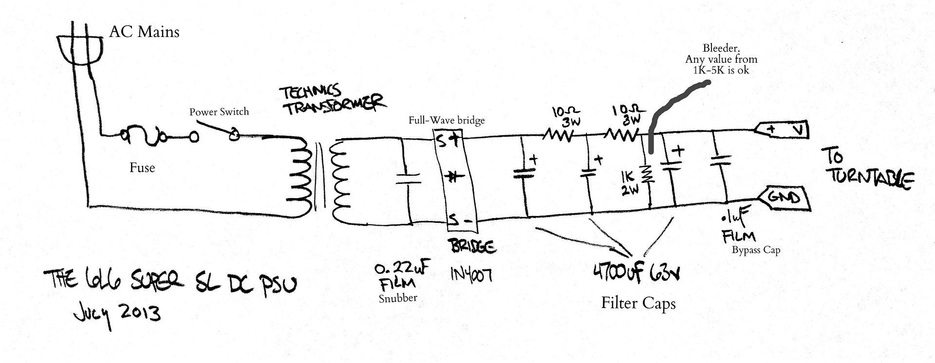
The schematic does show everything.
The Mains, fuse, AC switch.
Transformer.
Diode snubbber cap to the left of the bridge, and then the bridge.
The 4700uF caps with the 10 Ohm resistors for the CRCRC filter.
The film bypass cap and the bleeder resistor.
I will label the drawing.
Last edited by 6L6; 10-07-2013 at 21:33.
 Posting Permissions

 Reply With Quote