


This is my go at an external power supply for the SL-1200.
My most sincere thanks for this thread, it was extremely useful in this process - http://theartofsound.net/forum/showt...chnics-SL-1200
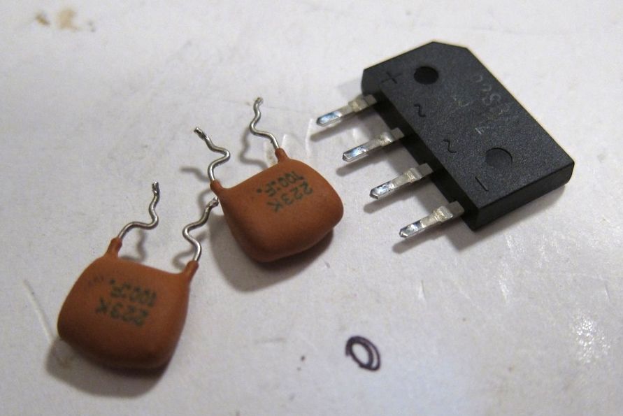
After a conversation with Wayne Colburn of Pass Labs, learning that he has made a SP-10 PSU for in-house use, a few things became apparent - Get the bridge diodes out of the TT and just have DC on the umbilical. Use 1N4007 diodes, for whatever reason they sound the best, even better than exotic high-speed diodes. Snub the bridge on the AC side with a .22uF film cap. Use multiple stages of RC filtering.
The biggest improvement is of course, no transformer vibration on the platter, easily done merely by locating the transformer outboard of the TT chassis, and this is what I was originally planning to do - but converting umbilical to DC wasn't much more work.
Does it sound good? Of course! And the best part is that I'm not even done yet, the stock regulator hasn't been replaced... (mainly because I ran out of time...)
UPDATE - The first regulator modification can be found here --http://theartofsound.net/forum/showthread.php?26620-SL-1200-DC-Power-Supply-DIY&p=467311#post467311
-------------------------------------------------------------------------------------------------------------------------------------------------------------------------------
--------------------------------------------------------------------------------------------------------------------------------------------------------------------------------STOP!
Before you put yourself or others in danger, think very carefully about whether you are qualified to carry out any of this work.
Art of Sound Electrical Safety Advice
The Art of Sound is an open forum for music lovers and a place where all members can share their views on music and the equipment used for its reproduction.
The forum also caters for those who are interested in the DIY aspect of everything related to the audio replay chain, and therefore there will always be a healthy number of DIY articles and discussions in threads across the forum. Given the number of these, it is not possible to monitor or moderate all technical aspects of posts made by members.
The Art of Sound would therefore like to remind all who read such articles that while we encourage discussions on all audio related DIY we cannot and will not accept liability for the information given on any DIY related matters contained in any thread or posts herein.
We strongly advise extreme caution when considering any modification or building projects described, especially those concerning any mains voltage related upgrades, earth modifications and/or any other high voltage related modifications or building projects.
Unless you are suitably qualified or otherwise capable of carrying out such modifications/suggestions, then we strongly advise you consult qualified personnel.
We would also like to remind all our members and readers that some or all of the modifications found within the threads and posts of the forum may not be legal in certain countries and therefore advice on the legalities or otherwise should be sought before carrying out such modifications.
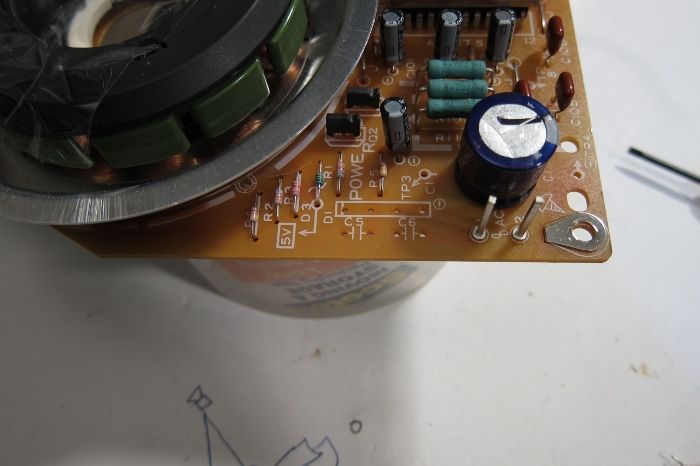
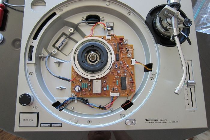
The first thing to be done is remove the bridge diode and snubber caps.
These were located in the holes now visible.
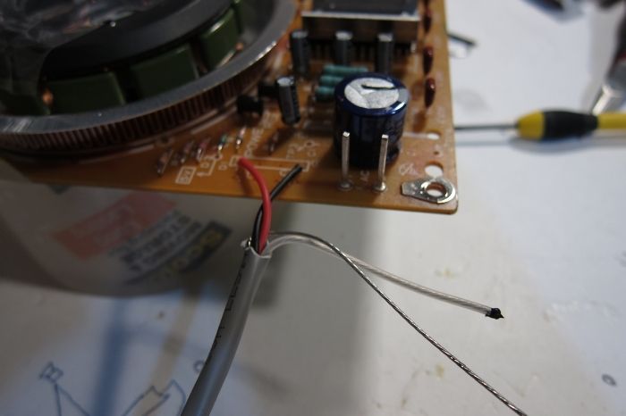
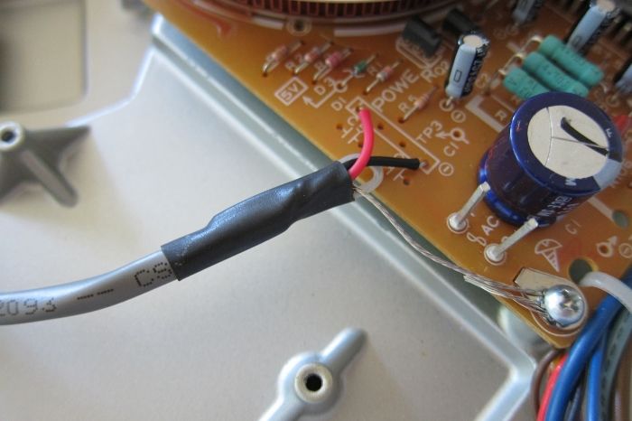
An umbilical is added. The white 3rd wire is capped off, but still there if I need it for something in the future. The bare metal wire is the shield drain, to be attached to ground.
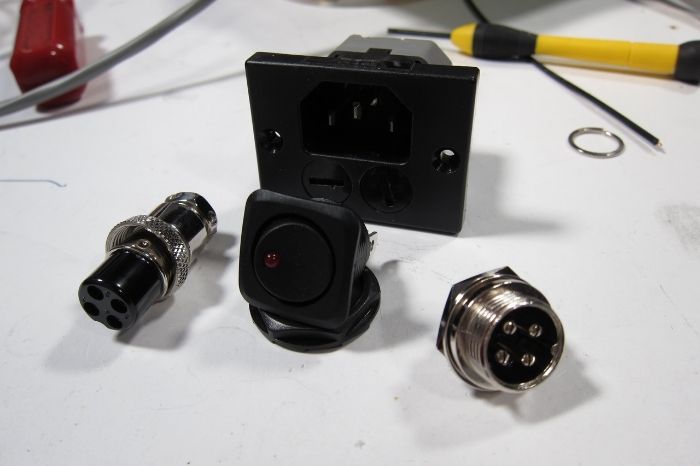
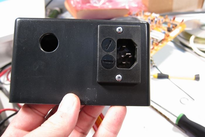
Fused IEC plug, switch, microphone connectors used for the umbilical.
All to be placed into this ABS enclosure.
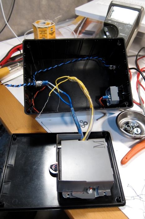
There is no reason not to use the stock transformer, it's the proper voltage, soft-mounted, has a beautiful mu-metal shield, and is free with the purchase of a turntable.
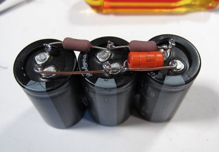
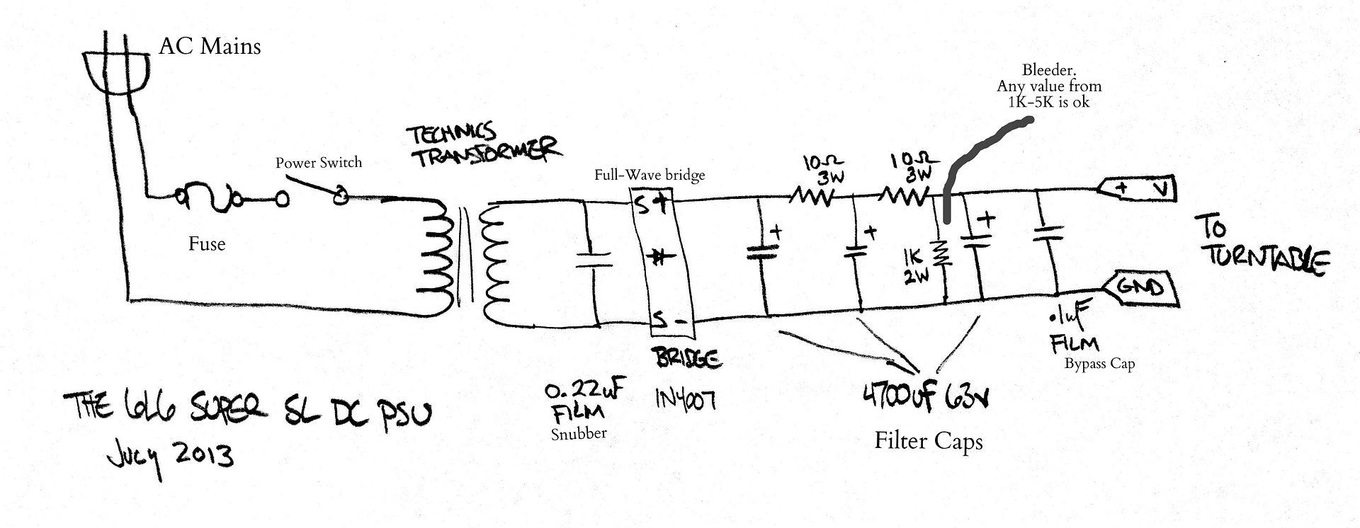
(3) 4700uF 63V volt capacitors, (2) 10ohm 3W resistors, .1uF polypropylene bypass cap, all wired up in a CRCRC filter. Why those values? I had them on hand. If I needed to buy new, I would probably use similar values.
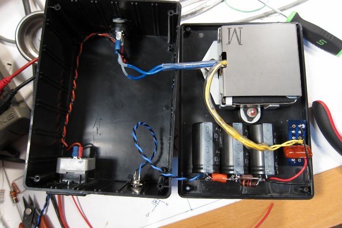
And here it is with the bridge to the side. (The yellow is the transformer secondary.) The eagle-eyed among you will notice the 1K bleeder resistor across the cap bank.
The final configuration of the umbilical attachment to the PCB. Of note the shield drain wire (the bare one) is not connected to anything at the PSU box. The shield is just at ground potential.
The insides after the modification. I utilized the now unused AC power switch to switch the strobe.
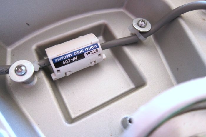
A few zip ties to attach the wire to the studs for strain relief, and of course the obligatory ferrite clamp.
Schematic of the Power Supply.
This is stage one of my PSU modifications, a different regulator of some sort will be next.
Questions or comments warmly solicited.
Thank you for looking.
 Reply With Quote

 Alan
Alan
 Originally Posted by 6L6

