+ Reply to Thread
Page 8 of 29 FirstFirst ... 67891018 ... LastLast
Results 71 to 80 of 285

Thread: SL-1200 DC Power Supply DIY

  1. #71
    Join Date: Aug 2012

    Location: Denver, Colorado

    Posts: 458
    I'm Jim.


  2. #72
    Join Date: Sep 2012

    Location: Gloucestershire, UK

    Posts: 90
    I'm Adam.

    Default

    I'd just like to say thanks to Jim who has been putting the parts list together for me. It is much appreciated

  3. #73
    Join Date: Jan 2013

    Location: Carlisle - UK

    Posts: 2,083
    I'm Ken.

    Default

    "thanks to Jim" +1

  4. #74
    Join Date: Feb 2008

    Location: Down South

    Posts: 2,411
    I'm Neal.

    Default

    Quote Originally Posted by 6L6 View Post

    Schematic

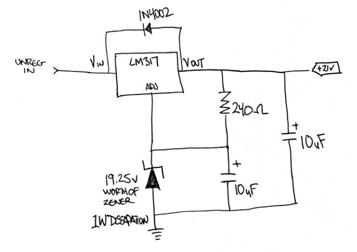
    You can usefully improve this circuit by increasing the current through the Zener, with R1 at 240R you are only passing 5.2mA. The Zener impedance and noise will drop further and the LM317 will work better if you use the recommended value of 100R for R1...this will increase the current to 12.5mA, the Zener dissipation will rise to 240mW but its well within its rating.

    You can increase the output voltage a touch and get temperature compensation 'thrown in' by placing a normal diode in the ground leg of the Zener, this will raise the voltage from (19.25+1.25) 20.5v to 21.1v....all as per the acoustica.org.uk site.

    Also one tip take is to the Adj pin ground connection to the load directly IE: don't connect to the nearest ground point but ground it at the load itself...
    Listening in a Foo free Zone...

    Only a Sith deals in absolutes.

  5. #75
    Join Date: Aug 2012

    Location: Denver, Colorado

    Posts: 458
    I'm Jim.

    Default

    Neal,

    Great info!

    Why does the zener noise decrease with an increase in current? I'm not familiar enough with this to know about it. I will give it a go when I wire it up on stripboard.

    I like the idea of the temp compensation with a 'normal' diode in the reference string as well. (Which will help trim the voltage, as I'm using a string to get to the reference voltage...)

    As for the ground, the idea of putting it straight to the load is quite sound. But where would that actually be on the motor board?

  6. #76
    Join Date: Jan 2013

    Location: Carlisle - UK

    Posts: 2,083
    I'm Ken.

    Default

    Jim – I am trying to do a layout for the regulator. Any chance you could update your schematic to show how the THREE zener diodes on your parts link connect up to each other and the rest of the components?


    I can see from the last couple of posts that this may still be under development, but the info would at least allow me to do my layout on paper.

    I am going to mount the components on a Paxolin board using solder eyelets and do point to point wiring on the reverse side – similar to one of my other projects here:


    I have drawn up the components from your list at full size and will arrange them on the board to suit, when I know how from your schematic. I am going to mount the board using the same fixings used for the regulator holding strap and this picture will give you some idea of what I am trying to achieve:

    http://www.jkwynn.co.uk/Project_Imag..._Regulator.pdf


    For anyone looking for a piece of insulation to go under the regulator, Farnell do a purpose made piece for the version we are using. Trouble is they’re presuming we are using the mounting hole. They also do a larger version for another application. You can cut off the ear for the mounting hole, leaving a large enough plain rectangle to fit under the LM317 with space to spare.
    Find it here (pack of ten £1.42):

    http://uk.farnell.com/multicomp/mk33...238?Ntt=520238

  7. #77
    Join Date: Aug 2012

    Location: Denver, Colorado

    Posts: 458
    I'm Jim.

    Default

    Ken -

    The diodes go in series in the same spot shown as the zener diode. I'll draw out something... but you have to understand that schematics are not layout diagrams. You could lay out a handful of components tens or hundreds of different ways and it be the same electrically.

    Also this would be a better choice for insulator, it's actually the right size for the 317 - http://uk.farnell.com/jsp/search/pro...note-520214-pr

  8. #78
    Join Date: Jan 2013

    Location: Carlisle - UK

    Posts: 2,083
    I'm Ken.

    Default

    Thanks for that Jim, I can work from that information, though no doubt you will update your schematic for us all at some point.

    The parts I have drawn are free standing sub assemblies, so I can move and rotate them till I am happy that I have a space efficient layout, that allows point to point wiring, without any wires having to cross each other. I have allready gone through 6 possible layouts with a single Zener, but I wasn't completely happy with any of them. When I get it right I will update the PDF file to show what I have done, you can have a look see before I warm up the soldering Iron.

    The insulator you link to is the one I mentioned and had rejected. It requires the use of a fixing screw through the mounting hole and the insertion of the insulating grommet on the screw which normaly aligns the regulator and insulator sheet holes. We do not have a fixing hole on the Technics (unless you drill and tap one) so there is no insulating gromet at the fixing hole, just air insulation and very close proximity between the walls of the hole on the regulator and the Technics mounting platform. This may be down to 0.3mm or less depending on the clearance hole allowance and whether you exactly align the regulator and spacer without it moving. I know the platform is painted and we are talking low voltage and amps, but I would feel better with a physical barrier of 0.1mm Mica, rather than the very small air gap and paint. Just my preference.

  9. #79
    Join Date: Feb 2008

    Location: Down South

    Posts: 2,411
    I'm Neal.

    Default

    Quote Originally Posted by 6L6 View Post
    Neal,

    Great info!

    Why does the zener noise decrease with an increase in current? I'm not familiar enough with this to know about it. I will give it a go when I wire it up on stripboard.

    I like the idea of the temp compensation with a 'normal' diode in the reference string as well. (Which will help trim the voltage, as I'm using a string to get to the reference voltage...)

    As for the ground, the idea of putting it straight to the load is quite sound. But where would that actually be on the motor board?
    Jim, the answers are in the acoustica pages. Also on the Ron Elliot site he talks about setting the current of the zener at 25% or slightly above of its rating so as to operate it at its most linear point which a 100R resistor would just about do or you could bump the current up a touch more if you felt like it.

    http://sound.westhost.com/appnotes/an008.htm

    Re the ground connection, I'm not sure, I don't know the circuit layout. What is the regulator powering? It maybe just fine with the original connection point.
    Listening in a Foo free Zone...

    Only a Sith deals in absolutes.

  10. #80
    Join Date: Aug 2012

    Location: Denver, Colorado

    Posts: 458
    I'm Jim.

    Default

    Neal, thanks for the update! I will change the resistor on the next go, and research more. (Although with 3 zener in series to get the desired voltage, it's probably not going to get in the 'sweet spot' of dissipation...)

    The regulator powers the +21V rail, most of the circuitry is downstream of the reg. The stock reg finds ground though the control and reference circuitry, which needs to be bypassed (by simply not connecting it) when using a new regulator. The easiest way to do this is run a wire back to the TT center ground, as shown in the photos.

    Also, please check your PM.

+ Reply to Thread
Page 8 of 29 FirstFirst ... 67891018 ... LastLast

Posting Permissions

  • You may not post new threads
  • You may not post replies
  • You may not post attachments
  • You may not edit your posts
  •