+ Reply to Thread
Page 1 of 4 123 ... LastLast
Results 1 to 10 of 35

Thread: A quick visual guide to externalising PSU from your Technics SL 1200

  1. #1
    Join Date: Aug 2010

    Location: Bergerac, France

    Posts: 567
    I'm Francois.

    Default A quick visual guide to externalising PSU from your Technics SL 1200

    Good afternoon everyone,

    After doing my home work and getting delivery of an upgraded Inspire Hifi platter, it had become essential to externalise the PSU as the plastic cover was well in the way.

    Sonddek from PFM did a great post here http://www.pinkfishmedia.net/forum/s...d.php?t=101356
    on doing so. A great walkthrough and very efficient at getting the job done.

    So I am not wanting to redo what he did, just merely doing a longer step by step for people less DIY minded (like me!).

    Usual precautions should be taken, and as Sonddek said himself SAFETY FIRST! Electricity isn't a TOY!

    ''I advise anyone who is not very clued up about electrics NOT TO DO WHAT I'VE DONE HERE, as there is plenty of scope for killing yourself or burning your house down when everyone has gone to bed.''


    Onto our first picture, our shopping list from MAPLIN.

    All in all, it costed 26 GBP! In time of recession, you won't get any cheaper for an external PSU!
    Tools required are your box standard set of screw drivers, pliers, cable cutter and stripper, a 30W soldering iron, some good quality solder, a bit solder wick or a solder sucker! A hammer, some blu tak, a fair bit of patience and more essentially a clean and well lit worktop!

    The main challenge when opening up your TT and revealing the motor PCB and its satellites, nominally the Traffo, the Regulator, the PSU PCB, is to understand where the power comes from and where does it go to... So basically the IN points in each PCB...

    So, first we need to isolate the PSU and Traffo from the mains.

    In this picture, we clearly see the black mains cable being soldered to the 2 AC posts. We just need to desolder them and clean them to remove any old bits of wire. This is the IN point for our PSU PCB.

    Then onto the IN point for our Motor PCB.

    These 2 posts are basically where the current enters the Motor Board. Just unwrap the cables carefully, there is usually no solder there. So an easy one.

    Next is just a little bit of tidying up.

    We need to unsolder that thin blue cable, because further down the line we shall be soldering our very own cable at that point of the PSU PCB. You can either keep it, or discard, but we won't use it...

    OK, before we can completely remove the Traffo and the PSU PCB, we need to disconnect the ON/OFF switch (the on located on top of the Strobe turret).

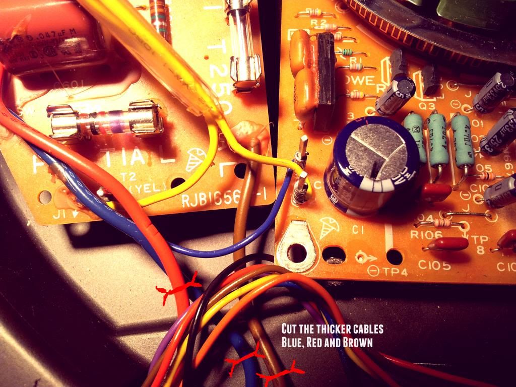
    Here just isolate the 3 thicker cables coloured Blue, Brown and Red. Make sure you don't confuse them with the smaller gauge ones which are feeding the speed switches, the light turret, the strobe turret and the pitch slider.
    Just cut those 3, tidy them away to avoid any contact with moving parts.

    At that point we can safely remove the screws holding the Traffo and PSU PCB. And lift the 2 units out of the Turntable.

    2 things need to be done at that point, first we need to connect the remaining bits of the Brown cable to the remaining bit of the Blue cable. The reason for this is since we disconnected the ON/OFF switch we have left an open loop on the PSU PCB, by soldering these 2 together we are basically resolving this problem. To prevent any shortening, cover the soldered end with a neat bit of heat shrink.
    Secondly we need to remove the loose end of Red cable. Just unsolder it. It's good practice, but has no electrical impact on the modification.

    Moving on swiftly to our next set of mods...
    So, now we need to attach the newly released parts to our new casing.

    Just roughly position both parts onto the base, and use a very small phillips screwdriver, position it through each intended hole and tap with a hammer to imprint the correct position for drilling later on. Just to be clear, the Traffo needs 3 holes, the PSU PCB needs 2. The PSU PCB has got a little screw printed next to the correct holes (as seen in my first 2 pix). DON'T attach screws to any other holes as you might connect to a live part of the PCB!

    Onto a little bit of drilling,

    We don't need tremendous power and speed to drill through the plastic case. A normal drill bit for wood will do, and just make sure not to drill at too fast a speed, slowly does it! Secure the pieces of plastic with blu tak on your work top. And off you go! We are using M3 screws to secure Traffo and PSU PCB, so a 3mm drill bit will do a beautiful job.
    Don't forget to drill also the lid with one hole at each end for Power cables to enter the casing...

    To secure the PSU PCB you will need to add a couple of bolts and discs. (All included in the Maplin pack listed at the beginning).

    Excuse the really crude drawing, just to illustrate the idea that the PSU PCB shouldn't rest directly on the floor of the new casing.


    Now is time to start reconnecting things together.

    In this picture we first reconnect the mains black cable to the 2 posts we desoldered earlier on. See ref picture. Then we need to feed the Blue cable, (from the new black cable connecting our case to the TT), to the PSU PCB. Here you might have to drill the entry point a bit as it could be a little tight. Use a 2mm drill bit at very slow speed, making sure the board is well secure.
    The other strand form that cable connecting the PSU to the TT should be Brown and we need to tie it to the Traffo yellow cable left loose earlier on.
    A bit of heat shrink, and cable zip tie to leave things real tidy here...

    Then onto our final bit of reconnecting, our newly created link between PSU and TT needs to be attached to our 2 poles left open earlier on.

    Make sure you use just enough cable here, as you wouldn't want a loom of unwanted power cable lying beneath the spinning platter!

    Here is a wider pix.

    I have added a little ferrite ring here for ultimate RFI rejection... I am not sure it will do anything, but it kind of helps attaching the cable at the bottom of the TT.

    And That's It really, after that all you have left to do is correctly dress cables with zip ties, making sure nothing is loose, or could get potentially loose...


    Well, I hope this will help a few more people getting a really cheap and effective modification to this beautiful turntable that is the Technics SL 1200!!!

    Enjoy!
    Francois, Bergerac, France
    Source component/s:
    Musical Fidelity M1 Dac, Allo Digi One, Sony SCD-XE800, AVID Ingenium Twin arm, Audio Note Arm One, Groovemaster II 12in, Audio Note IQ3 MM, Denon DL103R MC, Croft Basic 25, TQ Iridium Phonostage, Puresound T10 Stepup Transformer, Zavfino majestic tonearm cable
    Amplification:
    Audio Note OTO PP, Dussun V6i
    Loudspeakers:
    Triangle Comete ES, Klispch RP600M
    Cables/stands:
    Quadraspire, Belden 9497

  2. #2
    Join Date: Nov 2010

    Location: Yorkshire

    Posts: 9,784
    I'm Andrew.

    Default

    Excellent. I like the idea of getting some small ferrite coils under the hood. Why didnt I think of that ???
    SS
    CD Teac VRDS25X(Audiotuned) DECK 1210 Mat Crystal Audio Mods MN Base/Bearing/Platter+Ebony armboard Feet Isonoe PSU Paul Hynes SR7EHD-27XL/DCSXL Ag DC lead/3 Stage Regs/Recap PCB+No Pitch/Strobe/Light ARM SME V(Kondo Ag Rewire&Tags) MC Cadenza Black FGS CABLES Arm Yannis SPD-4 IC Yannis 222 Litz+Ag bullets Power WAR PRE ATC SCA2 SPEAKERS ATC 50ASL STANDS Atacama PHONO Sugden Masterclass PA4 SUT Ortofon ST80SE POWER PSAudio P10

    VALVE / MONO
    PRE
    Croft Epoch(Modded) AMP Sondex S100 (Modded) SPEAKERS Tannoy 15"MG+RFC Warwick cabs+ Ref XO + Batpure supertweeters DECK Garrard 301 Mat Teunto Bearings 401(Bastin) Plinth Bamboo Arms 3009/3012 PSU Eagle+Tachometer MC Ag Meister II/FGS + Ortofon SPU MONO CABLES Arm Yannis 420.5 Litz+ SpeakerPC Tripple C+WBT-0681 Ag IC Oyaide FTVS-510 AgWBT 0110Ag Phonostages Paradise(4 Box Mega-Modded) / Croft Musicmaker


  3. #3
    Join Date: Nov 2012

    Location: Mechelen, Belgium

    Posts: 162
    I'm Karl.

    Default

    I don't know if the pictures are from your deck.
    But if so, while you're at it, replace C1 with 1000µF/50V.
    Have a look at the underside of the pcb, as you will notice, solder pads and holes are there to accommodate an axial cap, as the radial version will be too tall.
    A lot of decks are equipped with a 470µF/50V, while the schematic still states 1000µF (the correct value).
    No wonder that a lot of people claim impressive results with aftermarket psu's.
    Technics SL-1200 Mk2 recapped / MN bearing / Funk Firm Platter / Denon 103R / Lundahl LL1933
    Thorens TD 126 MkIII / SME Series III / Ortofon SME 30H // AT-OC9ML/II / Lundahl LL1681
    Thorens TD 160 / TP16 / Stanton 681SE

  4. #4
    Join Date: Aug 2010

    Location: Bergerac, France

    Posts: 567
    I'm Francois.

    Default

    Ah! Wonderful idea...
    It is my deck indeed, I did look at the service manual for values, but this one clearly was hidden right under my nose! I can see now the axial holes...
    Thanks for the tip!

    Don't you love a well engineered piece of equipment!
    Francois, Bergerac, France
    Source component/s:
    Musical Fidelity M1 Dac, Allo Digi One, Sony SCD-XE800, AVID Ingenium Twin arm, Audio Note Arm One, Groovemaster II 12in, Audio Note IQ3 MM, Denon DL103R MC, Croft Basic 25, TQ Iridium Phonostage, Puresound T10 Stepup Transformer, Zavfino majestic tonearm cable
    Amplification:
    Audio Note OTO PP, Dussun V6i
    Loudspeakers:
    Triangle Comete ES, Klispch RP600M
    Cables/stands:
    Quadraspire, Belden 9497

  5. #5
    Join Date: Nov 2012

    Location: Mechelen, Belgium

    Posts: 162
    I'm Karl.

    Default

    Quote Originally Posted by Frankyc2003 View Post
    Don't you love a well engineered piece of equipment!
    Oh yes I do.
    But I think Technics missed an opportunity to redesign the pcb after the mkII.
    Some (important) traces on the pcb are very long and the whole damn thing is not properly shielded.
    Imagine what they (the engineers) could've done with a double sided and properly designed pcb. In the 70's, it would have increased production cost, but in the 90's and later, it would have cost them next to nothing extra.

    My board, still waiting for PH regulators to arrive and still with the "old" motor driver chip:
    Technics SL-1200 Mk2 recapped / MN bearing / Funk Firm Platter / Denon 103R / Lundahl LL1933
    Thorens TD 126 MkIII / SME Series III / Ortofon SME 30H // AT-OC9ML/II / Lundahl LL1681
    Thorens TD 160 / TP16 / Stanton 681SE

  6. #6
    Join Date: Sep 2012

    Location: Kempele, Finland

    Posts: 74
    I'm Joni.

    Default

    Great tutorial, Francois!
    Thanks for sharing this information!
    Regards, Joni.

  7. #7
    Join Date: Aug 2010

    Location: Bergerac, France

    Posts: 567
    I'm Francois.

    Default

    Morning all, just a quick update pic to show the new uprated cap in place as suggested earlier. One thing to note, I had to tweak the brake on the PCB to restore a nimble Start/ Stop response. Otherwise all good.
    Oh and also just make sure you have good clearance between platter and new capacitor. Its a chunky one! Hence the tight fit!
    Francois, Bergerac, France
    Source component/s:
    Musical Fidelity M1 Dac, Allo Digi One, Sony SCD-XE800, AVID Ingenium Twin arm, Audio Note Arm One, Groovemaster II 12in, Audio Note IQ3 MM, Denon DL103R MC, Croft Basic 25, TQ Iridium Phonostage, Puresound T10 Stepup Transformer, Zavfino majestic tonearm cable
    Amplification:
    Audio Note OTO PP, Dussun V6i
    Loudspeakers:
    Triangle Comete ES, Klispch RP600M
    Cables/stands:
    Quadraspire, Belden 9497

  8. #8
    Join Date: Nov 2010

    Location: Yorkshire

    Posts: 9,784
    I'm Andrew.

    Default

    Francois,

    A man after my own heart, I had my pcb reapped as well. Just out of interest what differences are you expecting to see with the bigger cap?
    SS
    CD Teac VRDS25X(Audiotuned) DECK 1210 Mat Crystal Audio Mods MN Base/Bearing/Platter+Ebony armboard Feet Isonoe PSU Paul Hynes SR7EHD-27XL/DCSXL Ag DC lead/3 Stage Regs/Recap PCB+No Pitch/Strobe/Light ARM SME V(Kondo Ag Rewire&Tags) MC Cadenza Black FGS CABLES Arm Yannis SPD-4 IC Yannis 222 Litz+Ag bullets Power WAR PRE ATC SCA2 SPEAKERS ATC 50ASL STANDS Atacama PHONO Sugden Masterclass PA4 SUT Ortofon ST80SE POWER PSAudio P10

    VALVE / MONO
    PRE
    Croft Epoch(Modded) AMP Sondex S100 (Modded) SPEAKERS Tannoy 15"MG+RFC Warwick cabs+ Ref XO + Batpure supertweeters DECK Garrard 301 Mat Teunto Bearings 401(Bastin) Plinth Bamboo Arms 3009/3012 PSU Eagle+Tachometer MC Ag Meister II/FGS + Ortofon SPU MONO CABLES Arm Yannis 420.5 Litz+ SpeakerPC Tripple C+WBT-0681 Ag IC Oyaide FTVS-510 AgWBT 0110Ag Phonostages Paradise(4 Box Mega-Modded) / Croft Musicmaker


  9. #9
    Join Date: Mar 2010

    Location: Sheffield

    Posts: 2,899
    I'm Simon.

    Default

    Ferrite half way down the cable means half a radiating cable, put it as close to the point where it enters the chassis as poss.
    Kuzma Stabi/S 12", (LP12-bastard) DC motor and optical tacho psu, Benz LP, Paradise (phonostage). Imac m1, gustard A18dac, Bruno Putzeys balanced pre, neurochrome 486 dual mono amps, Yamaha NS1000m with raal ribbons

  10. #10
    Join Date: Jan 2008

    Location: Mid Lincs

    Posts: 1,445
    I'm Buffet-blower.

    Default

    Fantastic information Francois - thanks for sharing. Still not sure I'd tackle it myself (I just about know how to solder an RCA plug...and even then it's a bit hit & miss) but this half-whetted my appetite to give it a go on my 1210 which is saying something.
    Richard.

    Round & round bits: LP12/Cirkus/Kore/Herc II/Roksan Nima/Hana EL
    Megabits: Bluesound Node 2i/TEAC UD-H01 dac
    Making it louder bits: Phonostage: Dynavector P75 Amp: Cyrus 8vs/PSX-R Speakers: Royd Sintra II
    Connecting it together bits i/c's: Flashback Premier. Speaker cables: Van Damme Hifi

+ Reply to Thread
Page 1 of 4 123 ... LastLast

Posting Permissions

  • You may not post new threads
  • You may not post replies
  • You may not post attachments
  • You may not edit your posts
  •