A good result then.
You are fortunate to have a wife who has sufficient interest, to be able to hear differences.
My wife seldom comments on anything, unless i emerge from the garage with some ridiculously large home made speakers.

 Senior Member
Location: Chester
Posts: 429

A good result then.
You are fortunate to have a wife who has sufficient interest, to be able to hear differences.
My wife seldom comments on anything, unless i emerge from the garage with some ridiculously large home made speakers.
Last edited by Mike; 27-09-2008 at 11:20.
 Senior Member
Location: Hampshire
Posts: 330
Im back!
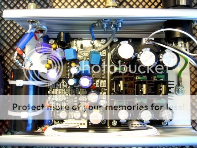
Here are a few more photos of my project.
Here is a list of the components changed so far...
C3 Jamicon 220uf
C18 Jamicon 220uf
C11 3.3uf Tant
C10 Vishay 0.1uf ERO 1837
C7 Vishay 0.1uf ERO 1837
C9 Vishay 0.1uf ERO 1837
C16 Oscon 150uf
C8 3.3uf Tant
C12 3.3uf Tant
C25 Oscon 150uf
C26 Oscon 150uf
C13 3.3uf Tant
C41 Wima 0.1uf
C19 Panasonic FC 2200uf
C21 Panasonic FC 470uf
C17 Oscon 150uf
Bypass caps are SCR 8uf with R68 resistors
Using standard JRC opamp and have also tried LM4562
The output sounds a little bit veiled and lacking sparkle. The internal coax is a 50ohm cable from Maplin. I was after 75ohm to match the 75ohm socket but the chap at Maplins said it would not make any difference because the cable length was so short.
Leo recommended keeping the transformer close to the DAC. Do you think I have mine too far?
Can you recommend changing any of the parts to help improve the sound?
Thanks
Richard
Senior Member
Location: Hampshire
Posts: 330
Hi StifaOriginally Posted by STIFA

Sorry for taking so long to respond I have been up to my neck in solder!
The two black caps are SCR 8uf coupling caps for the output. These were pinched from a pair of speaker cross-overs.
How are you getting on with yours?
Richard
 New Member
Location: Poland
Posts: 14
I'm Hidden.
There is my project.
DAC is built in to the Cambridge Audio D500SE. Original output stage is unusable for me, so I decided to build tube stage. It's SRPP using E88CC. Sounds very good, far better than original opamp based circuit.
Photos and comments:
-purple frame original trafo moved to make room for additional trafo (for tubes)
-green frame additional trafo for tubes
-yellow frame filament supply
-red frame anode supply
-turquoise-coloured frame DAC board
-pink frame tube output stage
http://www.audiostereo.pl/zalaczniki/1167490_1.jpg
http://www.audiostereo.pl/zalaczniki/1167490_2.jpg
http://www.audiostereo.pl/zalaczniki/1167490_3.jpg
New Member
Posts: 13
What are those great little tube PCBs and where can I get some. Nice job BTW.
Cheers
Rob
New Member
Posts: 13
Thanks for the heads up on the FR. Did you change the resisters as discussed by Leo in this post?
Where he suggests R8,R9,R14,R17 to 30k and C32,C33,C34,C35 to 150pf.
Last edited by fordgtlover; 28-09-2008 at 04:46.
 Senior Member

Location: Surrey
Posts: 7,227
I'm Rob.
Has anyone tried to connect a clock to this board?
New Member
Location: Poland
Posts: 14
I'm Hidden.
What are those great little tube PCBs and where can I get some. Nice job BTW.
Cheers
Rob
Thanks.
"Those great little tube PCBs" are custom made in Poland.
New Member
Posts: 13
Do you sell them?
New Member
Location: Poland
Posts: 14
I'm Hidden.
I don't sell them. I buy them ;-)
 Reply With Quote