


Lenco Based Turntable Project
I've heard some great idler drive turntables over the years and always wanted to try one myself. The likes of Garrard and Thorens have got to very high prices recently and more than I wanted to spend. I came across various articles singing the praises of the Lenco L75 (GL75 in UK) and after some research over at the Lenco Heaven website, I decided this model would be a good way into the world of idler drives.
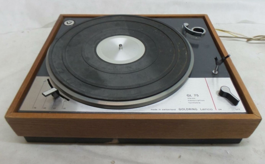
This was the donor deck I purchased off eBay, no arm and a rough looking plinth, but fully working.
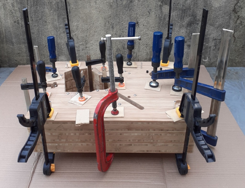
I built a new plinth from three 40mm slabs of Bamboo worktop. My purchased material is A1 quality, with no voids or filler, but expensive. I found a kitchen supplier selling A2 offcuts at reasonable price, I think these were the cut outs for double basin sinks etc, so scrap.
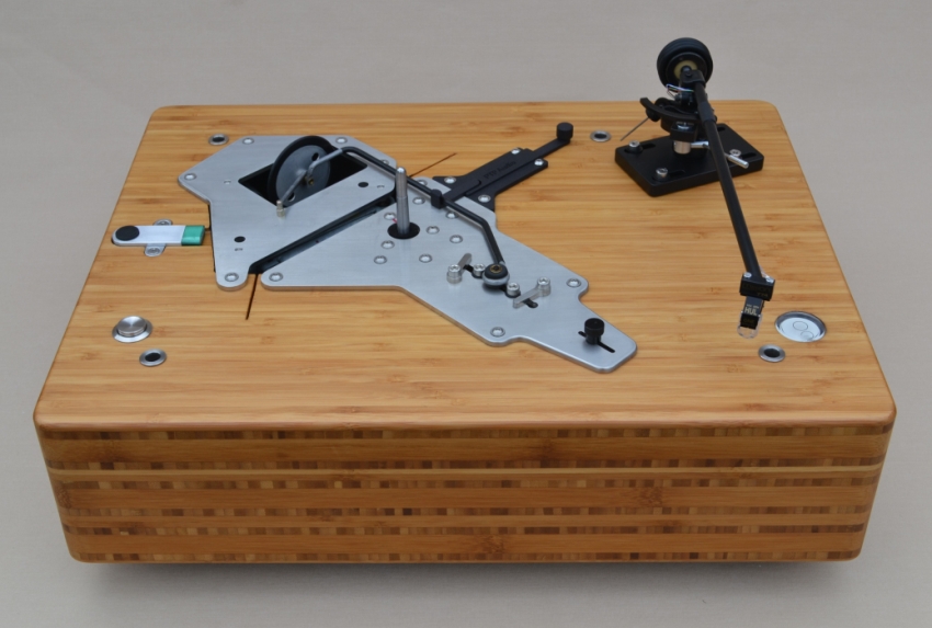
I used the PTP6 stainless steel top plates available from the Netherlands and an upgrade bearing made by SPH (Malaysia), I built an additional bottom bracket to support the bearing both ends.
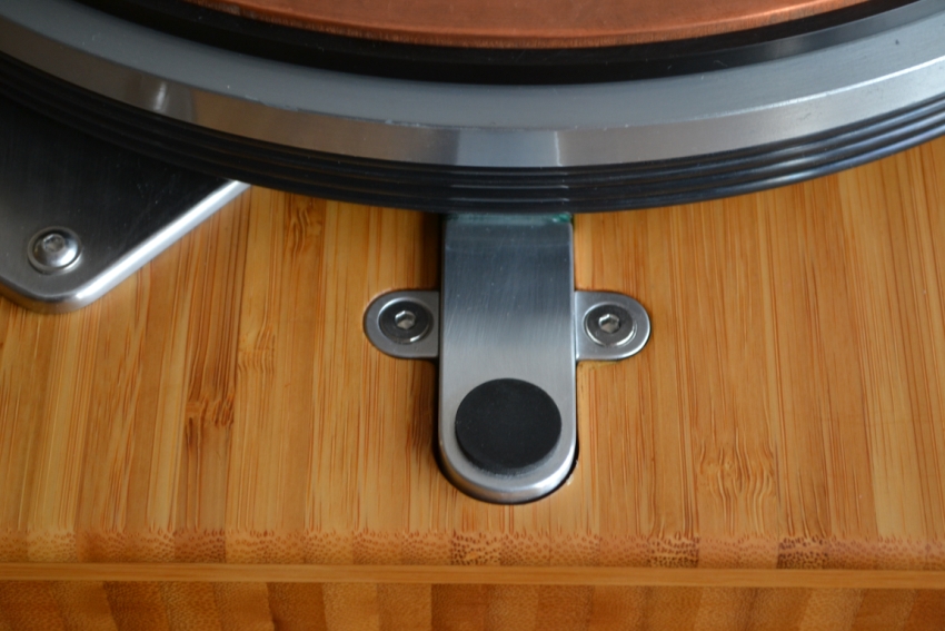
With a good bearing, these heavy platter decks can take over a minute to come to rest when the motor is turned off. This can be a pain when changing records, so I designed/built a brake, which brings the platter to rest in less than one revolution.
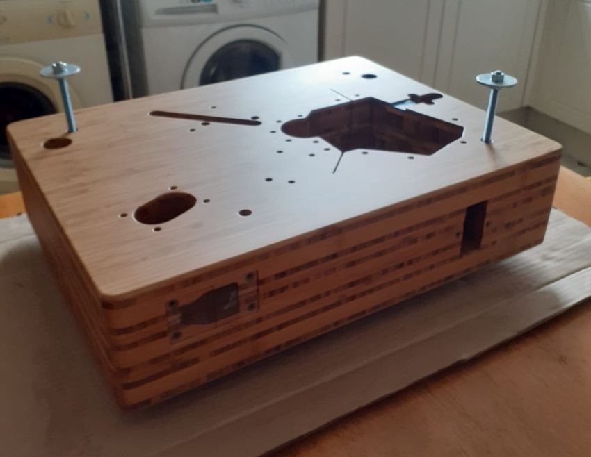
I added a spirit bubble and feet, adjustable from the top face, to make it easy to set up and finished the deck in Satin varnish.
Tonearm
Similar to my hankering for an idler drive, I've always wanted to try the original Mission 774 tonearm and I managed to obtain a very nice example from a member of this parish. Just like this:
Anyone who has followed my projects knows I like to do things my own way, so modifications were bound to happen. The arm is very well engineered, so no fear of me touching anything that would upset that. However, the base plate has no way of adjusting the Spindle to Pivot distance and the method of holding the arm stub, in a relatively thin plate, with a single grub screw is not the best, so I made my own base for the arm to drop into.
I rewired the arm with “The Missing Link” and my cartridge of choice was the Van Den Hul ONE Special. This is a good compliance match for the arm and the cartridge has a healthy current output, important for my fully balanced current amplifying AQVOX 2Ci phono stage.
Fitting the arm was not without its problems.
There is conflicting and confusing information on the internet regarding the set up for this arm, some of it from Missions own documentation. The only dimension I could trust, was the effective length of 229mm which is in the specification info that comes with the arm. I set out with this in mind and using the other dimensions for offset and S to P being quoted on the net. This was the result.
As you can see, the cartridge leads exit the arm wand under the holding clamp. If it were tightened in this position it would trap and probably damage the wires.
Something is seriously wrong here, the effective length seems about 10mm to short for my wand. I was confident it was the original Mission badged wand that came with the arm. Made with a double wall tube, most replacement wands are single wall. With all the conflicting information I decided to create my own geometry, using the alignment program on vinyl engine.
First step was to measure the offset angle of the mounting block on my specific arm wand, as there was a variety of dimensions being talked about on various forums, from 20.5deg to 22deg. I created a measuring template, which other owners might find useful and is linked here:
https://www.jkwynn.co.uk//774/Pics/L...fset_Angle.pdf
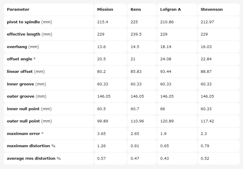
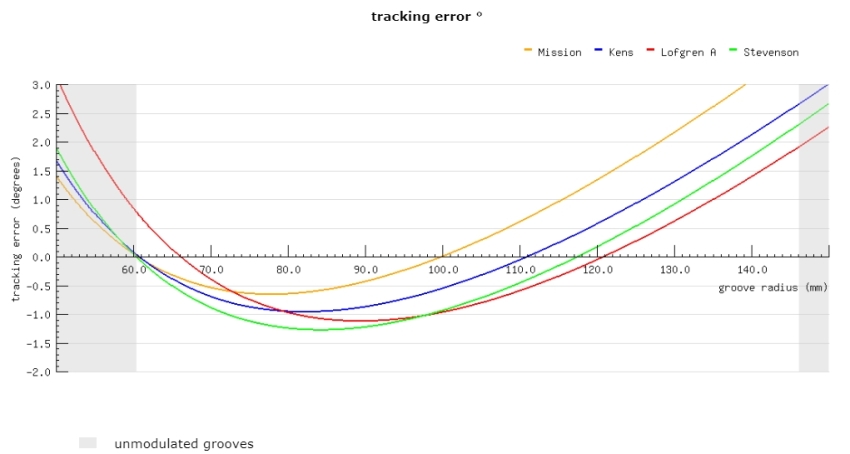
My mounting block has a measured offset of 21deg, so this would be locked into the settings of the alignment program as a non variable and the Spindle to Pivot and effective length, which are adjustable, would be tweaked in the program. The following results and comparison with the presumed Mission, Lofgren A and Stevenson geometry were produced.
As can be seen my Geometry seems to have better results than the presumed Mission dimensions, in terms of tracking error and distortion. The cartridge sits square in the mounting block and the wires now exit the wand in front of the clamp, like this:
It's early days, I used a basic set up, with the stylus pressure in the middle of the range, Azimuth and VTA were handled with a spirit bubble on the mounting block, so I haven't dialled in the sweet spot or tried the paddles/damping oil, but it all sounds very nice regardless. A very black background and lack of surface noise (on a good record) tends to suggest the alignment is a good one.
My wand is 247mm long, measured along its centre line, to the middle of the front face of the cartridge mounting block. Should anyone else have the same issues I faced, with a wand of similar length and offset, you might want to try my alignment. The only down side, is my S to P distance has increased by 9.6mm, not a problem for my adjustable base, but the stock base will need re-mounting at the new distance. The values are:
Spindle to Pivot = 225mm
Effective Length = 239.5mm
Offset Angle = 21deg
The protractor I created can be found here: https://www.jkwynn.co.uk//774/Pics/L...Protractor.pdf
I'm just enjoying the way this combination of turntable arm and cartridge work together.
If you want a blow by blow account of the plinth build or arm mods/alignment, find the Project on my web site here: https://www.jkwynn.co.uk/Lenco/Lenco_Thumbs.html


 Reply With Quote
 .
.

 Greatly admire your new arm base and height adjustment attachment. Well done!
