+ Reply to Thread
Page 5 of 47 FirstFirst ... 3456715 ... LastLast
Results 41 to 50 of 470

Thread: CS4397 dac

  1. #41
    Join Date: Apr 2008

    Location: Chester

    Posts: 429

    Default

    Iain.

    Depends how confident you are with a soldering iron. The board has survived a couple of attacks from me, but there's always a danger of lifting PCB tracks.

    The ceramic surface mounts are reckoned to be good with digital so i'd just bypass em for the time being.

    The input cap C9(another ceramic which doesn't sound bad) can be improved on. I've been doing an experiment with different bypass caps for C9. Haven't really finished yet,(been at it for a week or so) but have discovered that some caps which can sound wonderful in analogue applications, don't seem to cope with high frequency digital information.
    Exceptions are Obbligatto caps and Vishay/ERO 1837 which live up to expectation. Both of these improve on the original. Even a cheap tantalum sounded quite nicely balanced.
    I tried a red Wima here but it sounded muffled especially at the bottom end.
    Anything polyester sounded awful.
    The clear winner amongst those tested so far, would have been a 0.33uf Ansar polyprop which has stunning clarity at the top end, but in this application, very weak bass.
    Of course you may find that different values yield better results, but i have a feeling that very low inductance is important here and that's why the big Obbligatto cap works better than other big caps.

    I even tried bypassing the bypass cap in an effort to get a good compromise, but then things start to deteriate. To be expected.

    Next step is to remove the original C9 and see which one works best in its place.

    Good luck.

  2. #42
    Join Date: Apr 2008

    Location: Cheltenham U.K

    Posts: 412
    I'm John.

    Default

    Quote Originally Posted by iihay View Post
    What's the best approach with smd caps, am I ok just sticking the new cap across it or is it better to get the little blighters off first?

    Cheers

    Iain
    I found it quite easy to remove the smd caps by heating them with the iron and then just sliding them off. You can then get a good, reliable connection between the new component and the pad.

  3. #43
    Join Date: May 2008

    Posts: 34

    Default

    Thanks chaps, I'm not too bad with an iron after my recent amp build so I should be ok. Keep us posted on the C9 experiments, I don't have too many caps lying around to do this kind of trial and error so I am very interested to hear how it goes.

    Cheers

    Iain

  4. #44
    Join Date: Apr 2008

    Location: Chester

    Posts: 429

    Default

    A good reason to leave C9 in place for the time being, is that you then have something to use as a reference. As i found out after trying several different caps, you need to be able to compare with the surface mount.

    It's quite difficult to remember the sound of a cap for any length of time.
    Having narrowed it down to four, things should be easier.

    If a particular capacitor sounds good as a bypass, then theres a reasonable chance it will be good in place of C9.

  5. #45
    Join Date: Apr 2008

    Location: Cheltenham U.K

    Posts: 412
    I'm John.

    Default

    It seems to me it would make sense to look at C24 in conjunction with C9, since both are part of the SPDIF input circuitry.

  6. #46
    Join Date: Apr 2008

    Location: Chester

    Posts: 429

    Default

    Good point, C24 is on my list of things to do. It hasn't been touched yet because i didn't want to fill the board up with caps and find out i couldn't get access to anything.

    C9 is a real pain to get at, when trying to fit a chunky cap as close as possible to the board. I might remove the onboard input socket since i'm not using it. That should help quite a bit.

    Having slagged off polyesters in a previous post, i now find that the little "orange drop" types work rather well. Don't usually like these, but they're not bad here.

  7. #47
    Join Date: Apr 2008

    Location: Cheltenham U.K

    Posts: 412
    I'm John.

    Default

    Has no-one else tried to use this at 96kHz? Mine still won't play ball and I'd like to know why. By the end of next week I expect to see your clear answers, in good English and with no spelling mistakes. (Stern headmaster smilie would be here if we had one!).

  8. #48
    Join Date: Apr 2008

    Location: Chester

    Posts: 429

    Default

    I'm sure Lee will come in when he can, Seems to be having a spot of bother with his PC at the mo.
    I can't answer your questions.

  9. #49
    leo's Avatar
    leo is offline Circuit Junkie & DIY Room Forum Leader
    Join Date: Jan 2008

    Location: Notts UK

    Posts: 1,804

    Default

    Don't talk to me about PC's

    TBH I've not tried 96khz, reason being I don't have any 96khz material , I mainly use a modified SB3 to feed the dacs and its limited what it can output.
    I'll have to look at the dacs datasheet, apart from this cheapo pcb I've not used the CS439* family before, could be to do with how they set the mode control on this board, the PLL was wrong so who knows what other mistakes there is


    Have you tried another dac to be sure the digital signal is actually 96khz?
    Last edited by leo; 08-06-2008 at 16:02.

  10. #50
    leo's Avatar
    leo is offline Circuit Junkie & DIY Room Forum Leader
    Join Date: Jan 2008

    Location: Notts UK

    Posts: 1,804

    Default

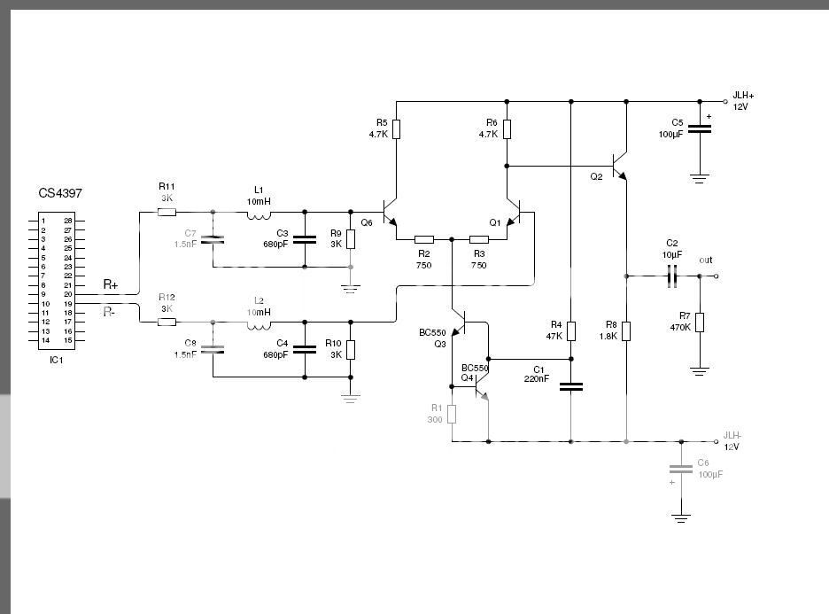
    Just knocked up this output stage to try

+ Reply to Thread
Page 5 of 47 FirstFirst ... 3456715 ... LastLast

Tags for this Thread

Posting Permissions

  • You may not post new threads
  • You may not post replies
  • You may not post attachments
  • You may not edit your posts
  •