-
 CS4397 dac
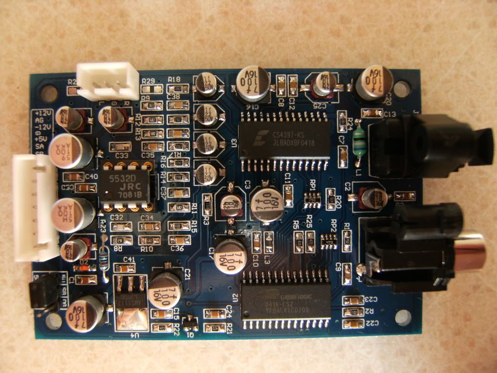
I got one of these cheap dac pcbs to play about with, its based on the CS4397.
I've changed the PPL filter for the CS8416 as I noticed it was the wrong values, it now locks onto the spdif much better and sounds better too.
I have also changed the op-amp to a OPA2111 and bypassed the coupling caps on the dacs differential output
Voltage is being supplied from ALW super regs
Sound so far isn't bad, its quite a way behind both my diy TDA1541A double crown based dac and diy PCM1794 based one but we'll see how it goes with some more work, never been a huge fan of voltage output dacs but its all good fun
I'm going to build a discrete differential to line out output stage so to ditch the op-amp, also have a play about with the decoupling
Replace the phono in socket for the spdif to a 75R BNC and probably add a pulse traffo on the input
Edit added 01/06/09
I recently had a PM from a forum member under the name of Raptor , he's spent some time going through the mods and thought it would be helpful for others to compile list and info so here it is
- R2 becomes (BC Components minimelf) 3k, C22 becomes 22nF, and C23 becomes (COG/NPO) 1 nF ((Read datasheet for reccommendations))
- Remove and link the pads of the 4 DAC output capacitors, (2.2u 50v C27,C28,C30,C31)
- Remove and link the pads of the output capacitors near RGL socket (10u 16v C6,C54)
((Use your own MKP))
- Link the two exposed pairs of pads underneath on the top and top left of the small IC ((This bypasses it completely.))
- C9 (C7/C13 for TOSLINK) should be REMOVED and replaced by a Vishay/ERO MKP1837 0.1uF or equivalent. (Possibly also a small 0.1uF Ceramic dipped in hot glue to remove some microphonics. SHORT LEADS)
- Lift or unbridge pin 2 of the CS4397 and connect to Pin 16 of the CS8416.
- R8,R9,R14,R17 to 30k WELL MATCHED
- C32,C33,C34,C35 to 150pf SMD or Polystyrene
- R28 and R29 should be missing.
- C17,C20,C2 100uf-220uF Oscon
- C16 100uF Oscon
- C3, C18, C11 can be left alone (Just pulling pins high)
- C25 5.6!!-10uf Tantalum or 5mm MKP.
- C12, C8, C13, C10, C14(C41) bypass with MKP 0.1uF
- C19 should be 1 decimal step smaller than the last filter cap on your +5 supply. (1000ish Not OScon.)
- C21 should be 1 decimal step smaller than C19. (100-220ish Not OScon.)
- Tube out - http://theartofsound.net/forum/showp...&postcount=325 or page 33.
- Digital out - Pages 22-27ish have a board layout referenced from earlier page's schematic. 30-35 have modifications to the components around the opamp socket for output. I suggest just pulling off the DAC's 2.5+v outs with a coupling cap or trafo.
"BTW don't always trust what you read regarding low ESR caps, their not always better in every application" -Leo
Last edited by leo; 01-06-2009 at 16:19.
Tags for this Thread
 Posting Permissions
- You may not post new threads
- You may not post replies
- You may not post attachments
- You may not edit your posts
-
Forum Rules





 Reply With Quote