+ Reply to Thread
Page 1 of 35 12311 ... LastLast
Results 1 to 10 of 345

Thread: Technics 1210 internal regulation mods

  1. #1
    leo's Avatar
    leo is offline Circuit Junkie & DIY Room Forum Leader
    Join Date: Jan 2008

    Location: Notts UK

    Posts: 1,805

    Default Technics 1210 internal regulation mods

    I think almost everybody who tried a high quality external regulated psu appreciated the improvements in sound quality it made over the Technics stock supply , I was very impressed with the PH PR3G3HD-21 diy based supply, it was certainly worth the effort imo.
    A few of us have been discussing why not try taking things further ? The plan was to install a pair of 21v high quality regs inside the Technics to supply the motor and its drive circuitry separate from the rest of the circuitry instead of the shared voltage from the external regulated psu . We then increase the output of the external regged supply to allow for the voltage drop needed for the new internal regulation to work.
    Paul Hynes designs the best regulation I've come across so was pleased to find he can supply the PR3 modules without the rectifier , this makes them about half size of the full AC input module and makes them a good fit inside the Technics.
    The PR3DC-21 DC input modules are suited for the standard 1200/1210 platter , the PR3DCHD-21 are higher current and suited for both standard platter and Mike New platter .

    Heres what I've done so far

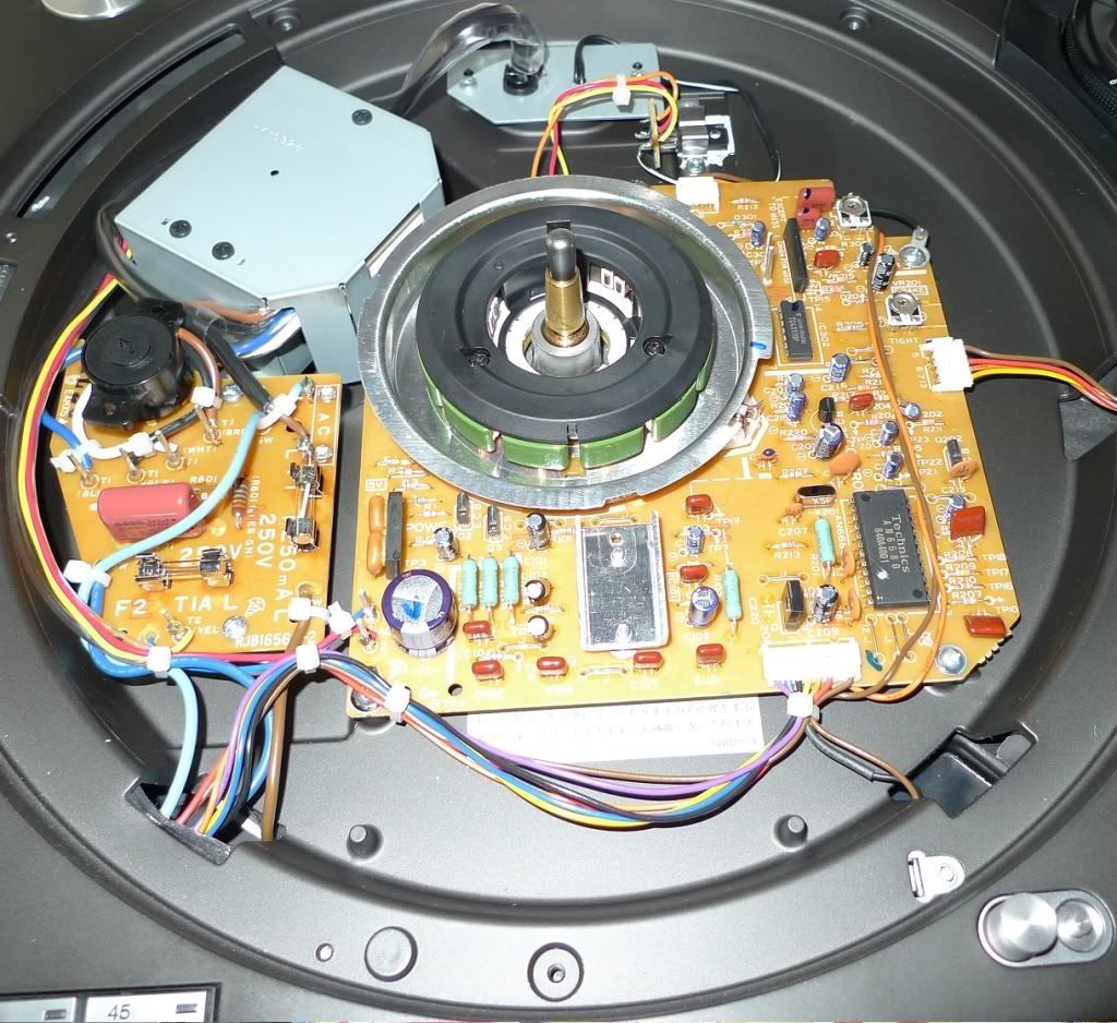
    Inside the stock 1210


    Transformer + shield removed, pcb removed


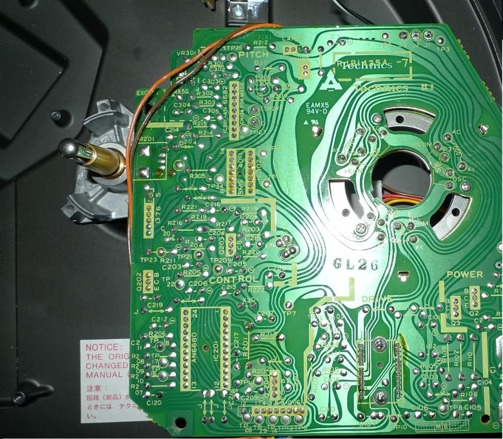
    Bottom of pcb after removal , be careful removing the wired plug in sockets and all the screws


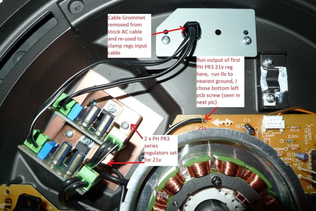
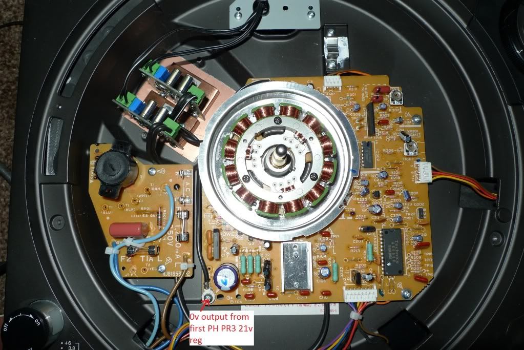
    Separate Paul Hynes PR3DCHD-21 series regulators adjusted for 21v output fitted in the space where the stock transformer sat , I bolted both regulators to a piece of copper clad board to keep them together as a temp fix, some form of mounting plate would be better long term.
    The output transistor (part of stock regulator ) was also disconnected and removed.
    The top 21v PR3DCHD-21 regulator supplies the main (top half ) of the pcb , the bottom 21v PR3DCHD-21 regulator now supplies the 21v bottom half (motor and its circuitry )


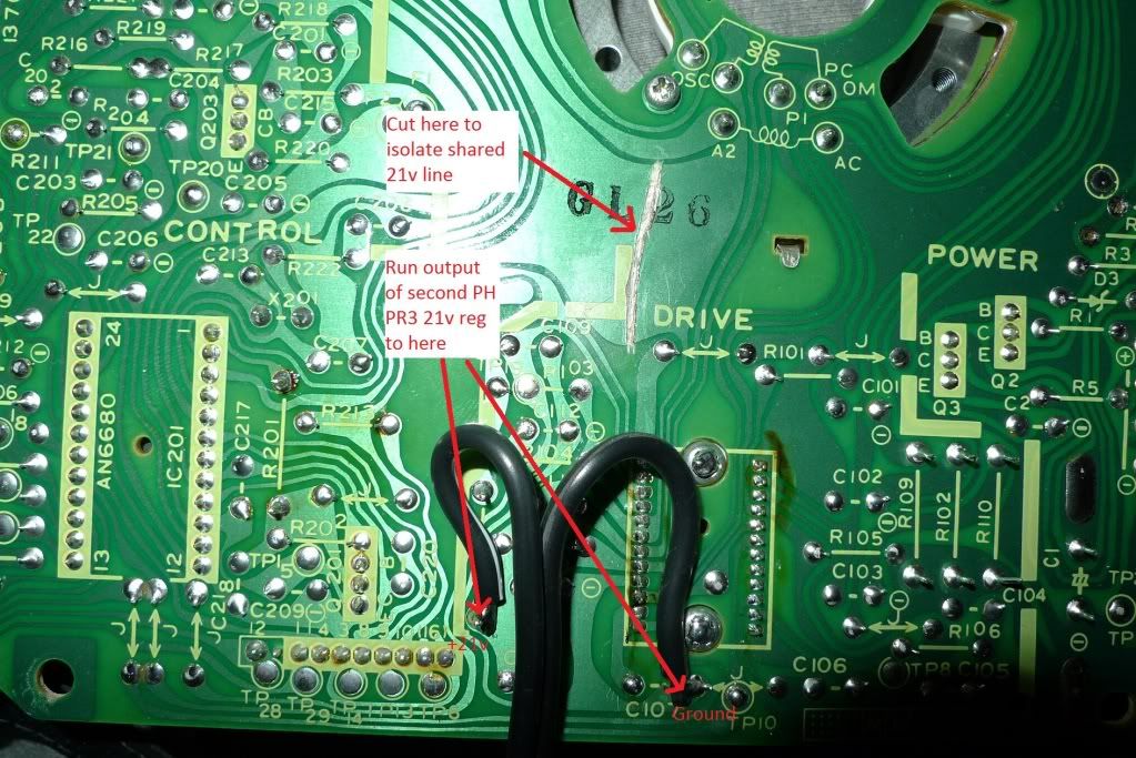
    Bottom of pcb showing track cut isolating the second part of circuit supplying motor and its circuitry , the black cable is from the output of second 21v PR3DCHD-21


    Top view showing pcb refitted , the regs in place, wiring etc


    The external regulated psu used now has to have its output adjusted higher to around 27v to give enough headroom for the newly fitted 1210 internal regs. I built another PR3/5 based psu using the higher current PR3ACHD-27 (pics added later) and fitted a transformer with higher rated secondary voltages (the one I fitted originally only had 18v secondarys ) .
    The PR5 psu's simply need a small adjustment and don't require any component or transformer change. I also tried an external regulated psu based LM1084 which worked too, definitely not as good as the Paul Hynes module though.

    Going from the stock 1210 psu to the diy external one using the PR3G3HD-21 module http://theartofsound.net/forum/showthread.php?t=6043 improved the sound in all area's to my ears, infact tbh I was very impressed ! A thick veil was lifted and had reduced distortion, definitely tighter more tuneful bass and brought out more details in the high's. The whole thing sounded more musical and toe tapping.
    With the upgraded internal separate regs fed from PR3DCHD-27 there was noticeable improvements, not as large as going from the stock psu to the external one but I did notice a further layer of background muck (best way to describe it) removed, a little smoother in the high's and decrease in sibilance I used to hear on some recordings, bass gained a little more depth whilst remaining tight. All in all very nice.

    Swapping the external psu using the PR3DCHD-27 to the one based around CRC feeding a LM1084 also gave good results but to my ears the bass lost some impact and speed, it seemed to loose some of that wow factor it had with the PR3DCHD-27.
    Seems the main regged psu still has some influence even when the 1210 is using separate internal regs, I need to try out and compare a few more things yet so will update as soon as I can.

    I got all the price details for the regs from Paul for those interested

    PR3AC-21/27 standard AC input module £100
    PR3DC-21 standard DC input module £80
    PR3ACHD-21/27 higher current AC input module £120
    PR3DCHD-21 higher current DC input module £100

    Postage

    Insured carriage and packing for 3 modules is £10 in the UK, £14 in Europe and £20 to the rest of the world.

    Most other stuff like cable, case, transformer etc can be found from Maplin, RS and Farnell

    Added 07/01/2011

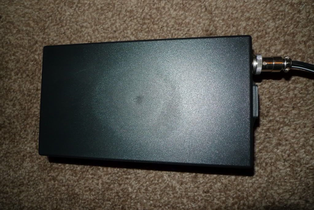
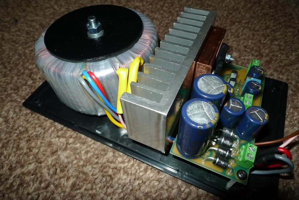
    A few pics of the external psu

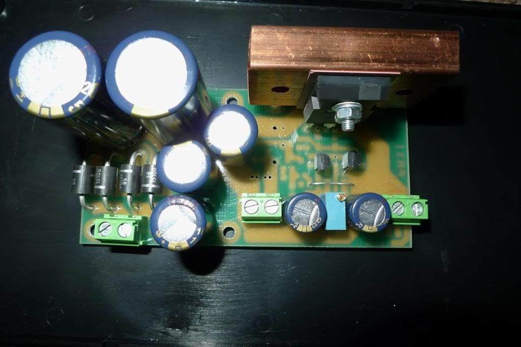
    Paul Hynes PR3ACHD-27 High current module


    Its all discrete! these are much more complex than a simple LM317


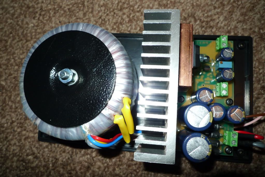
    Transformer and PR3ACHD-27 fitted to the cases base plate, the additional heatsink added is quite chunky, I fitted this for a reason
    I wanted to test this psu with a Virtue Sensation amp too which is classT based.


    Cables soldered onto the pcb pads bottom of pcb underneath the sockets


    Not the prettiest case but is the best I could get hold of, The Hammond ones wasn't quite big enough this time. I used 4pin lock plug and sockets to allow comparing DC cables later , sorting the cabling out properly will be done last

    Last edited by leo; 07-01-2011 at 21:20. Reason: Updated
    Cheers,
    Leo

  2. #2
    Join Date: Jul 2010

    Location: North Cambs UK, Earth, Sol, Orion - Cygnus arm of galaxy

    Posts: 11,166
    I'm MadeOfDeadGiantStarsThatExplodedEonsAgo.

    Default

    Hi Leo, a quick question for you

    There is a reasonable bit of wire between the regulators & where they connect to the PCB itself, don't you think there may be some benefit in some local bypassing on the PCB to lower the impedance?

    At about 20nH per inch of wire it might definately make a difference at least on the motor drive side of things. Less so with the control circuitry obviously due to a more constant current draw.
    Bests, Mark


    "We must believe in free will. We have no choice" Isaac Bashevis Singer

  3. #3
    leo's Avatar
    leo is offline Circuit Junkie & DIY Room Forum Leader
    Join Date: Jan 2008

    Location: Notts UK

    Posts: 1,805

    Default

    Hi Mark,

    As mentioned near the end of the starting post , theres still things to try out and compare yet . I'll be looking at things like bypassing etc (ta for the suggestion btw) . The pcb layout isn't exactly great ,the grounding tracks are all over the place so all we can do is improve things the best we can

    The regs output wire is about the thickest I could fit and quite meaty compared to the thin pcb tracks, I'm going to shorten the lengths on the output when finished , for now its easier to remove and re-fit the pcb with a little length on the outputs.
    Cheers,
    Leo

  4. #4
    Mike_New Guest

    Default

    Leo,
    Why not discard the terminal blocks and use directly soldered wire.
    It has been my experience in heavy current wiring of logic 5-Volt arrays that screwed terminals always quickly form some sort of electrolitic action which results in a higher resistance that is tollerable.

  5. #5
    leo's Avatar
    leo is offline Circuit Junkie & DIY Room Forum Leader
    Join Date: Jan 2008

    Location: Notts UK

    Posts: 1,805

    Default

    Hi Mike,

    Good suggestion ta, once finished I may do that, for now whilst trying other things the terminals along with the longer output wire makes removing the pcb easier. Once we are all satisfied its about as far as we can take the mods it'll be tidied up
    Cheers,
    Leo

  6. #6
    Join Date: Oct 2008

    Location: Scotland

    Posts: 366
    I'm Paul.

    Default

    Hi Leo,

    Thanks for providing the field trial for the internal regulator mods. I appreciate all the time and effort you have given to this project and the valuable feedback you have provided.

    Hi Mark,

    In an ideal world the regulation would be right on top of the load and each individual circuit section would benefit from it’s own regulation system. The twin regulator modification is designated as the level two upgrade for the power supply system. As Leo has stated, there is further work to do, and the results of this R&D will be made available when successfully completed. The modification levels are being designed to ensure there is no redundancy along the way so the financial investment of each stage does not reduce the value of previous stages. Remember I have been doing this sort of work for a long time. I already know how far I will be taking these modifications but each stage requires verification to ensure there are no unforeseen problems. This all takes time. I would not recommend something that was not a valid sonic improvement and I am quite sure Leo wouldn’t either.

    It is impossible to fit these regulator modules in the ideal position, due to lack of space, but the most important issue here is that the modification is a valid sonic upgrade, even though the wiring distance is not ideal, because it reduces inter-modulation between the control circuitry and the motor drive circuitry. Also a few hundred mm of wire between the regulator output and the load is better than a metre of wire from an external power supply.

    As it happens there is some local decoupling on the board and this could be upgraded with higher quality components. Also using a twisted pair of wires for regulator connection will help reduce inductive effects in the wiring. Once again the results of these trials will be posted once completed.

    Hi Mike,

    The regulator modules are fitted with screw/clamp terminals because many of my customers request them and I can fit the modules in the soak test bay easily using these terminals. I prefer hard-wired connections myself and anyone else who does can remove the terminals and hard wire their favourite wire as they see fit. This is what DIY is all about. As Leo says it is very convenient to have the terminals available during field trials. They can be dispensed with once the trials are over.

    Regards to all,
    Paul
    Paul Hynes Design
    paulhynesdesign.com
    High Performance Power Supply upgrades
    http://theartofsound.net/forum/showthread.php?t=16655

  7. #7
    Mike_New Guest

    Default

    Hi, Leo and Paul and Others.

    I have a rather innovative suggestion for you.
    Studying the circuit diagram of the PCB and the Logic Block Diagram today, it would be apparent that supplying a 9.4 DC voltage to the AN6680 control chip and the Q203 Rotation Sensor Amplifier transistor would provide even better performance.

    The AN6680 is fed by a frequency crystal, which could also benefit.
    Studying the Logic block diagram, it is apparent that the 9.4 V is derived from an internal regulator on the AN6680, which drives the Q201 which is in series with the 21volt main rail.

    Now if we split the 9.4V/21V circuit at this point we could then feed the 9.4 volt rail from our in chassis regulator at this point. Leaving the rest to be fed by the 21V supply which would be only the AN6675 Motor Control chip and the speed selector and strobe illuminator if used. The single Quad two-input NAND gate, which requires 5.6V for some reason, is regulated down from the 21V by a Zenor Diode and resistor.

    If one required to be really exact, then we could supply a second 21V to feed the NAND gate and the Speed Selector and Strobe, also Stylus Illumination lamp.
    In actual fact, the majority of the control circuits are fed by the internally regulated 9.4V supply rather than the 21V

    Implementing a distributed power supply as above would surely be the ultimate in power control to the SL1200!! And not cost any more in components.

    What do you think?

  8. #8
    Join Date: May 2008

    Location: A Strangely Isolated Place in Suffolk with Far Away Trains Passing By...

    Posts: 14,535
    I'm David.

    Default

    All this tweaking almost makes you think that the Technics engineers were a bunch of idiots and didn't know what they were doing! This is far from the truth I think, so I'd advise extreme care with these drastic mods and make sure at least one of you actually measures what's going on, heavy platters or not, otherwise in attempting to fix supposed problems, you may actually make things worse. Sonic differences can be mis-construed you know -

    Oh ok, I'm coming over all "evil auntie" here, but please take care fellas with what you're doing and maybe buy a spare stock deck with which to compare - those add-on boards cost a heck of a lot for what appears to be on them, so if you can readily afford to purchase these, then you can afford a couple of hundred on a stock deck to temporarily use as a reference, which can be sold on later
    Tear down these walls; Cut the ties that held me
    Crying out at the top of my voice; Tell me now if you can hear me

  9. #9
    leo's Avatar
    leo is offline Circuit Junkie & DIY Room Forum Leader
    Join Date: Jan 2008

    Location: Notts UK

    Posts: 1,805

    Default

    I only post things which I feel are worthwhile ,I don't bother posting mods I've tried which I thought didn't bring any benefits .
    Theres been a lot of discussion about improving the internal regulation of this deck, somebody had to go a step further and actually try it I was hoping the thread may help the competent diyers interested in this mod or help those interested in doing the work for those not competent

    I understand engineers know what they are doing but everything has to meet a price point during the design process, we simply improve the parts which have been slightly compromised.

    Hopefully carry on the discussions later, its time for me Quorn roast
    Cheers,
    Leo

  10. #10
    Join Date: Oct 2008

    Location: Scotland

    Posts: 366
    I'm Paul.

    Default

    Hi Mike,

    Further regulation procedures are the next phase of the power supply upgrade. I have already stated that the work is not yet finished. I am in the process of preparing low power miniature printed circuit board versions of the PR3 regulator for individual regulation of each section that requires power in the control section. Finite available time means it is a slow process, rather like maturing wine, and rather than go in and do everything at once I prefer to do things in stages allowing the results of each procedure to be assessed.

    Past experience with multiple regulation techniques applied to multi-stage mixed signal circuit systems has proven the validity of separately regulating everything. Setting up regulation in tiers is very beneficial for reducing mains born interference and it helps to provide more consistent performance where dirty mains is an issue. I am not just looking at optimising one parameter with this power supply odyssey.

    Hi Dave,

    The Technics engineers were not a bunch of idiots. They had to design the deck for the real world at a price that was viable for the chosen market. This inevitably means compromise and they did this very well. I face the same situations with my consultancy work where in many instances I am given a design brief that includes a budget and I have to work out the best compromise for the design within this budget. I could easily do better if the budget constraint was removed and so could the Technics engineers.

    High performance power supplies are not beer budget products. In my experience, and many others, it’s so easy to hear the difference between a high performance power supply and a budget implementation that it would be hard to misconstrue the improvement.

    Out of interest, the add-on regulator boards use a lot of surface mount components on the track-side of the PCB, and the circuit is somewhat more elaborate than would appear from the topside view. Compared to a 3 terminal regulator application note solution they are more expensive. They are not manufactured by the million, but are carefully hand built to a high quality design that has been refined, with much time and money spent on R&D, over many years. This particular regulator design is building up a rapidly expanding cult following worldwide, and is being used in a wide variety of applications successfully. Significantly, none of my customers has ever returned any of my products using this regulator topology, under my 56 day, return if not satisfied guarantee. What I am selling is intellectual property fabricated into a physical product that works very well providing a very valuable performance improvement that obviously far outweighs the price I charge for my product. If this were not the case I would have a large number of dissatisfaction returns for this regulator product instead of zero returns.

    Regards
    Paul
    Paul Hynes Design
    paulhynesdesign.com
    High Performance Power Supply upgrades
    http://theartofsound.net/forum/showthread.php?t=16655

+ Reply to Thread
Page 1 of 35 12311 ... LastLast

Posting Permissions

  • You may not post new threads
  • You may not post replies
  • You may not post attachments
  • You may not edit your posts
  •