Can someone explain what this means please. Its certainly not the internal resistance of the cable.

 Senior Member
Location: Bishops Stortford
Posts: 1,250
I'm Chris.
Can someone explain what this means please. Its certainly not the internal resistance of the cable.
Last edited by bumpy; 14-02-2021 at 15:39.
Source
SW1X Universal Music Server UMS I Signature with Power Supply Unit PSU I Signature
SW1X USB II
SW1X DAC III Special
Audiolab 6000 CDT transport
Amps
Pre amps -- Hi fi Collective twin mono ladder stepped attenuator, with Charcroft Z-foil and silver wired. And First Watt B1 active no gain buffer.
Power amps -- Welborne 45 SET monoblocks 1.8W / Decware Taboo 6W / Elekit 300B TU-8600SVK plus further improved components 9W / ICE Power 1000W
Speakers
Highly modified Endorphin P17 open baffle speakers containing both vintage and modern alnico drivers and paper cones. All silver wired - 8" Cube Audio FC8 full range drivers and vintage 15" Altec VOTT 416 bass drivers. All sat on Townsend Audio Podium seismic isolation platforms.
BK Electronics XLS400FF Sub.
Cabling
Silver mains cables, interconnects and speaker cables by SW1X
Headphones
HRT HeadStreamer and SennHeiser HD650 headphones
Senior Member

Location: The Black Country
Posts: 6,089
I'm Alan.
At very high frequencies (much higher than audio) the capacitance and the inductance of the cable come into effect.
This capacitance and inductance is 'distributed' capacitance and inductance and can't be thought of as 'lumped' values, eg the total value of the capacitance for the length of cable.
These distributed values form an impedance that is directly related to the ratio of the diameter of the inner and outer conductors when considering a coaxial cable.
I love Hendrix for so many reasons. He was so much more than just a blues guitarist - he played damn well any kind of guitar he wanted. In fact I'm not sure if he even played the guitar - he played music. - Stevie Ray Vaughan
Senior Member
Location: Bishops Stortford
Posts: 1,250
I'm Chris.
I think I understand that
In terms of just carrying a signal, any interconnect seems to do the job, but what are the implications on SQ when using such a phono interconnect?
Source
SW1X Universal Music Server UMS I Signature with Power Supply Unit PSU I Signature
SW1X USB II
SW1X DAC III Special
Audiolab 6000 CDT transport
Amps
Pre amps -- Hi fi Collective twin mono ladder stepped attenuator, with Charcroft Z-foil and silver wired. And First Watt B1 active no gain buffer.
Power amps -- Welborne 45 SET monoblocks 1.8W / Decware Taboo 6W / Elekit 300B TU-8600SVK plus further improved components 9W / ICE Power 1000W
Speakers
Highly modified Endorphin P17 open baffle speakers containing both vintage and modern alnico drivers and paper cones. All silver wired - 8" Cube Audio FC8 full range drivers and vintage 15" Altec VOTT 416 bass drivers. All sat on Townsend Audio Podium seismic isolation platforms.
BK Electronics XLS400FF Sub.
Cabling
Silver mains cables, interconnects and speaker cables by SW1X
Headphones
HRT HeadStreamer and SennHeiser HD650 headphones
Senior Member
Location: The Black Country
Posts: 6,089
I'm Alan.
Put simply with mismatch reflections of the signal occur so the waveform gets ragged. This can cause issues associated with jitter dependent upon the tolerance of the receiving equipment.
Senior Member
Location: Bishops Stortford
Posts: 1,250
I'm Chris.
Thanks
Source
SW1X Universal Music Server UMS I Signature with Power Supply Unit PSU I Signature
SW1X USB II
SW1X DAC III Special
Audiolab 6000 CDT transport
Amps
Pre amps -- Hi fi Collective twin mono ladder stepped attenuator, with Charcroft Z-foil and silver wired. And First Watt B1 active no gain buffer.
Power amps -- Welborne 45 SET monoblocks 1.8W / Decware Taboo 6W / Elekit 300B TU-8600SVK plus further improved components 9W / ICE Power 1000W
Speakers
Highly modified Endorphin P17 open baffle speakers containing both vintage and modern alnico drivers and paper cones. All silver wired - 8" Cube Audio FC8 full range drivers and vintage 15" Altec VOTT 416 bass drivers. All sat on Townsend Audio Podium seismic isolation platforms.
BK Electronics XLS400FF Sub.
Cabling
Silver mains cables, interconnects and speaker cables by SW1X
Headphones
HRT HeadStreamer and SennHeiser HD650 headphones
Trade: Coherent Systems
Location: Gerrards Cross
Posts: 3,005
I'm Tony.
Sorry for the amount of posts here but its an important question and one I feel needs some in-depth answers.
These posts are part of a reply I produced for a technical forum a few months back, I am just so busy at the moment my time is really finite I will produce some interesting experiments over Christmas which will dig deeper into a broader range of cable impedance issues for you but for now some basic get you going stuff!
It is accepted that 50 Ohms is the T & E standard, the ideal transmission vector is calculated around 43ish which is why 50Ohm is used in pretty much all test equipment (except when looking at certain voltage rails we use 1M ohm test probes)
Coax impedance is anywhere between 20 and 120 Ohms depending on application required. Below is the formula for working out cable impedance's. However I use a Vector Network analyzer with Smith chart ability and also VSWR measurements to look at impedance characteristics of different cables AND connectors (materials also). For those VNA#s that do not have a 75 Ohms facility we use 50<>75 matched transformer Baluns.
Characteristic impedance (Zo) is the most important parameter for any transmission line. It is a function of geometry as well as materials and it is a dynamic value independent of line length; you can't measure it with a multimeter. It is related to the conventional distributed circuit parameters of the cable or conductors by:
Zo=√[(R+jωL)/(G+jωC)]
where: R is the series resistance per unit length (Ω/m)
L is the series inductance (H/m)
G is the shunt conductance (mho/m)
C is the shunt capacitance (F/m).
L and C are related to the velocity factor by:
velocity of propagation = 1/√LC = 3 × 10⁸/√ɛr
For an ideal, lossless line R = G = 0 and Zo reduces to √(L/C). Practical lines have some losses which attenuate the signal, and these are quantified as an attenuation factor for a specified length and frequency (Table 1.8 on page 29 shows these for coaxial cables). Table 1.9 on page 41 summarizes the approximate characteristic impedance's for various geometries, along with velocity factors of some common dielectric materials. The value 377 (120π) crops up several times: it is a significant number in electromagnetism, being the impedance of free space (in ohms), which relates electric and magnetic fields in free-field conditions.
Driving a signal down a transmission line provides an important exception to the general rule of circuit theory (for voltage drives) that the driving source impedance should be low while the receiving load impedance should be high. When sent down a transmission line, the signal is only received un-distorted if both source and load impedance's are the same as the line's characteristic impedance. This is said to be the matched condition. It is easiest to consider the effects of matching and mismatching in two parts: in the time domain for digital applications and in the frequency domain for analog radio frequency applications.
A great many DIY electronics enthusiasts tend to use these impedance converting devices, its not really a complete solution if you are looking for a true impedance match. Ideally all things being equal keeping the pathway the same Z all the way through from Tx to Rx.
I appreciate however that most of the after-market clocks are specific 50 Ohms.
When we measure a 75 ohm impedance path ways and cables we use a set of true 75 Ohm calibration tools and have our VNA or TDR devices set to 75Ohm. Totally understand 99.7% of audio users are not going to have this facility.
What I can do is set up an example of a 75 ohm cable being used with 50 Ohm measurement parameters, this will give you an understanding of how the reflections can be seen on the waveform.
Think of it like a converter from SPDIF<>AES or single end to balanced always something lost in translation I feel.
Will it be better than a total mis match 50<>75? possibly yes, possibly no, sorry for not being more definitive.
Coherent Systems
Real high end sound with musicality not hifi
Trade: Coherent Systems
Location: Gerrards Cross
Posts: 3,005
I'm Tony.
As promised some results from using impedance mis matched cables and adapters.
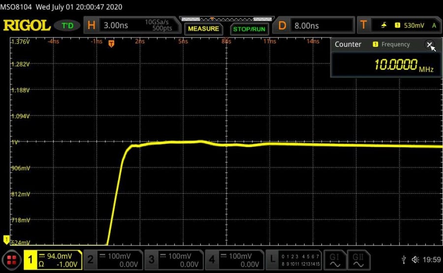
I used the lab's Mutec Ref10 SE-120 master clock as the signal generator, scope has been calibrated, all test cables 18Ghz reference ultra low loss 50 ohm, audio cables were 75 ohms matched. 50 Ohm adapter is an R&S reference 8Ghz model.
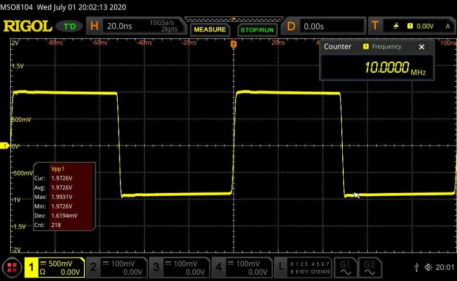
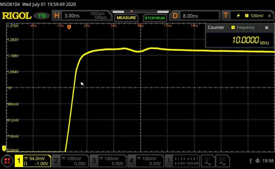
First images are a base line set, 50 ohm output, 50 ohm feed 50 ohm receiver, also I enhanced the waveform to highlight the very slight overshoot to give you an idea of of a close up of the wave form top edge definition.
Coherent Systems
Real high end sound with musicality not hifi
Trade: Coherent Systems
Location: Gerrards Cross
Posts: 3,005
I'm Tony.
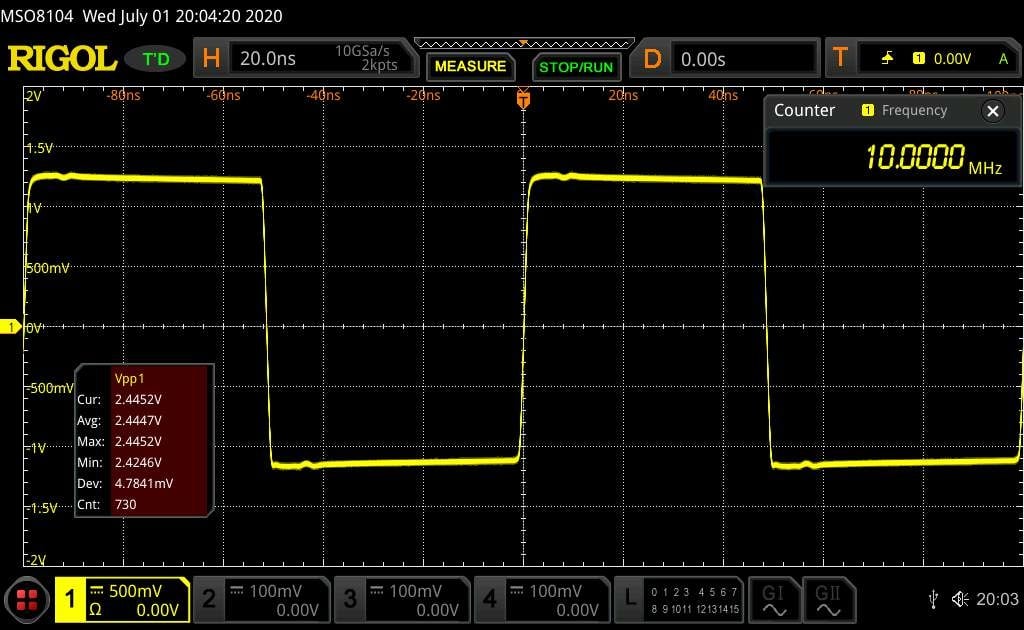
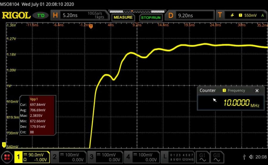
Next set of images show a 50 ohm cable being fed a true 75 ohm signal to a 50 ohm receiver note the reduced PK<>PK voltage and difference in the top edge wave form.
Coherent Systems
Real high end sound with musicality not hifi
Trade: Coherent Systems
Location: Gerrards Cross
Posts: 3,005
I'm Tony.
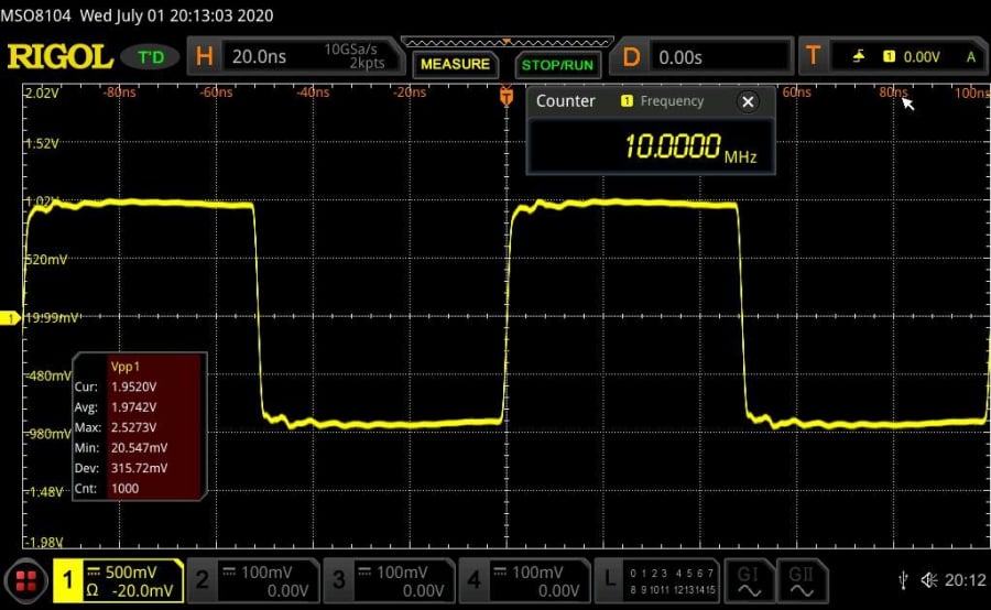
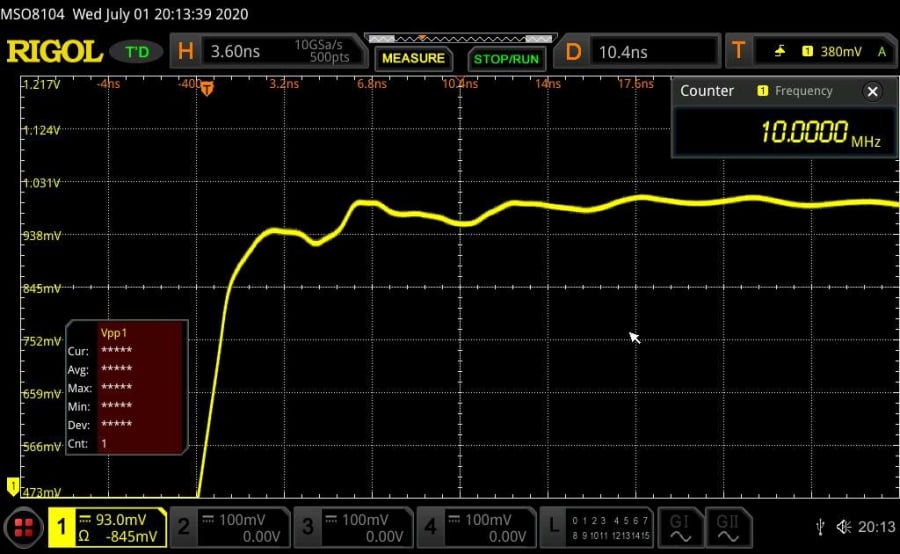
Now a genuine 75 ohm audio clock cable using the 50 feed into a 50 ohm receiver, as you can see plus the top edge definition again is greatly effected.
Coherent Systems
Real high end sound with musicality not hifi
Trade: Coherent Systems
Location: Gerrards Cross
Posts: 3,005
I'm Tony.
Last up 75ohm cable, 75 ohm feed into a 50 Ohm receiver, the lastly adapter added in to the chain for comparison.
As you can see the degradation of the wave form is pretty obvious, and especially with word clocks the wave form actually looks like a square wave form with very little deviations is the more ideal the situtaion.
Coherent Systems
Real high end sound with musicality not hifi
 Posting Permissions
 Reply With Quote