Very impressive figures Will.

 Captain Insightful
Location: Seaford UK
Posts: 1,861
I'm Dennis.
Very impressive figures Will.
Banned
Location: scotland
Posts: 330
I'm alan.
Hi Will.
Once this MA-100 beast becomes available, any chance of a trade in........???
Only kidding......The STA 25 MK5 is bloody stunning.
Trade: Radford Revival
Location: South West of England
Posts: 263
I'm Will.
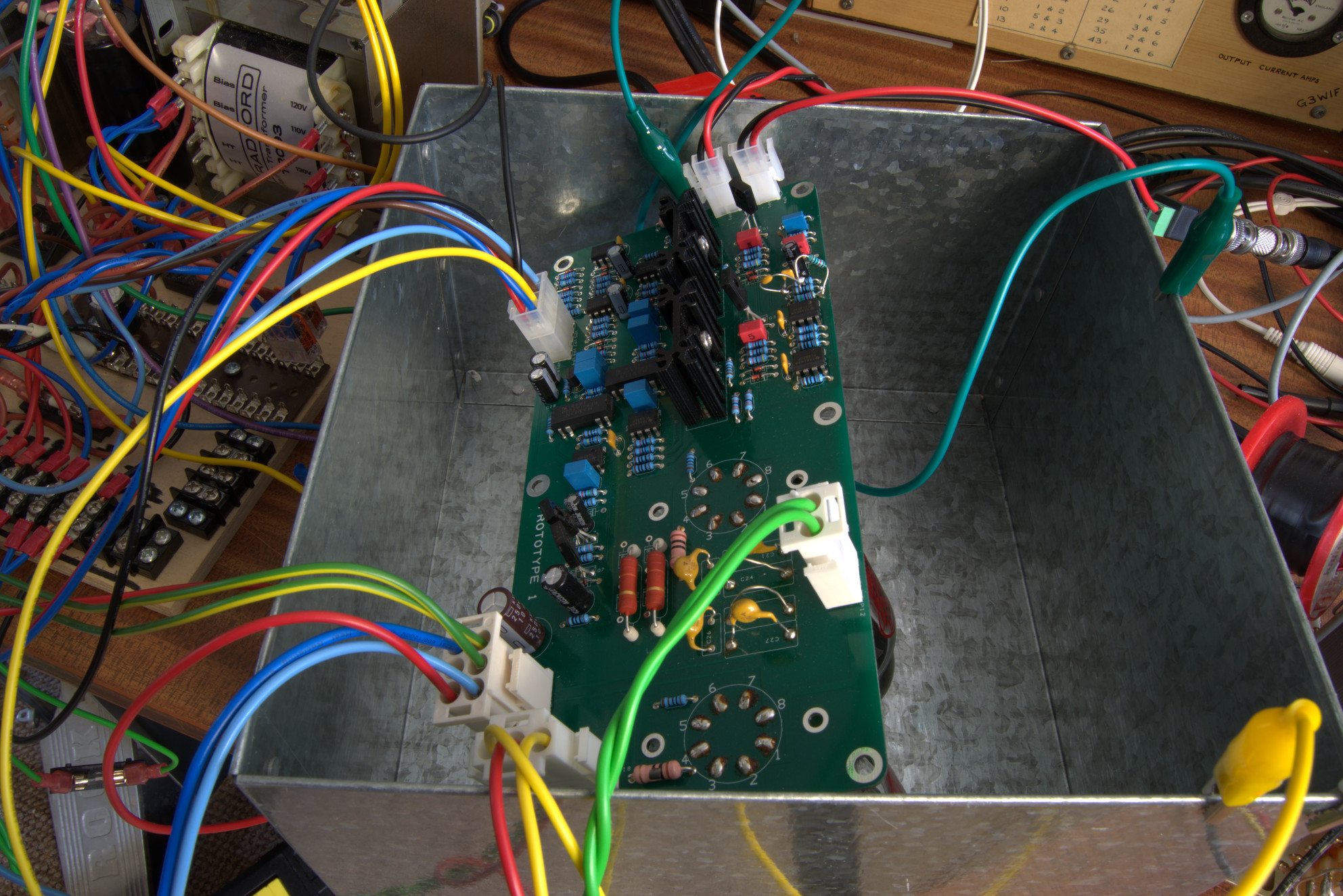
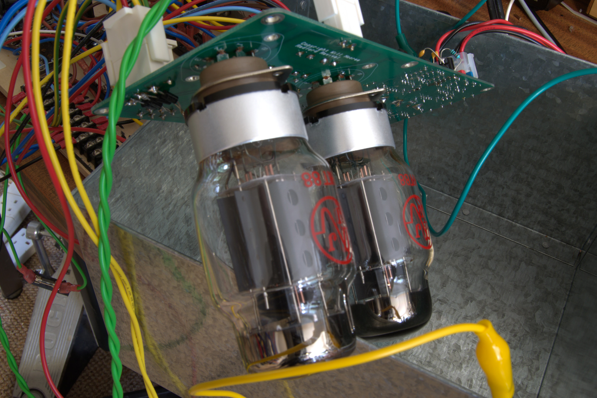
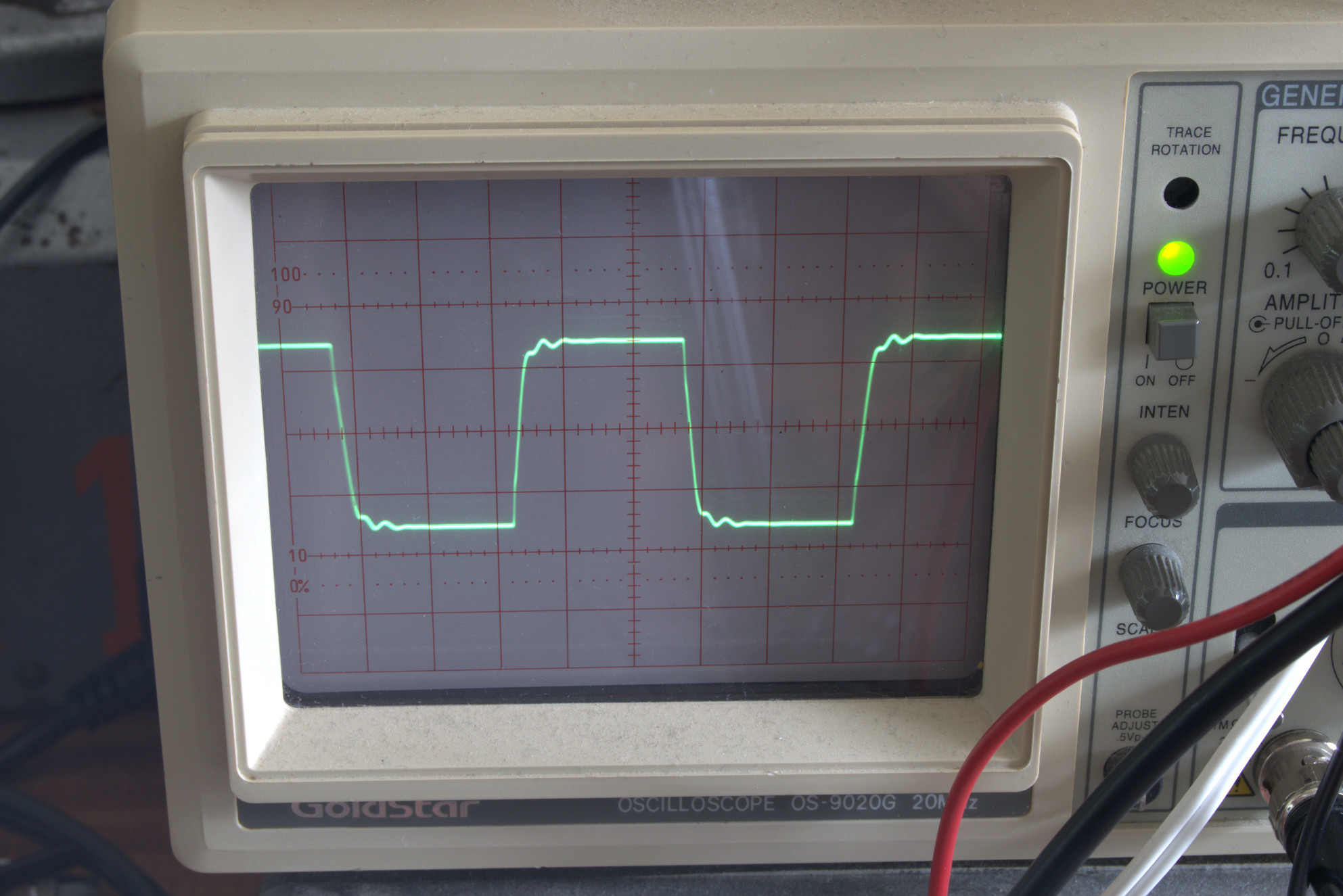
Pics of the prototype board + 10Khz small signal square waves. Note symmetry, fast rise times and suppressed resonance far above the audio band, somewhere around 150Khz. This could probably be tweaked out but I've not yet tried. If not for the squiggle it is more akin to an amplifier with no OPT at all!
This is with full bandwidth feedback applied.
What will hopefully lead to a very subjectively good sounding amplifier is that the IMD is so low as well as THD. With a 19+20Khz twin-sine test IMD remains around 0.1% - most tone combinations and mixing ratios hover around this level when approaching the power limits of the amp. At lower levels they are proportionally lower.
Recent tweaking has lowered mid-band THD to around 0.02% at full power (even 10Khz THD is 0.03% if you only look at the audio band!)
10W (i.e. where you'd mostly be using the amp) THD is around 0.005%, pretty much entirely just 2nd and 3rd harmonics, and a hundredth the level of many amps. That means 1 / 10,000th the power in distortion components than an amplifier giving 0.5% distortion. By no means state of the art by the standards of some of the latest solid state designs, I'd say this is pretty respectable for a valve amp!
Of course numbers aren't everything, and the circuit doesn't really go to any herculean efforts to get it that low, it is just the result of careful design around known sources of nonlinearity.
Radford Revival
www.radfordrevival.co.uk
Senior Member

Location: West Sūþsēaxe
Posts: 2,016
I'm Edward.
Looking and I'm sure sounding great Will. Impeccable build quality as usual.
§
Current: [P20] Roon/Tidal > Custom PC> Chevron Paradox NDF16 > Phast Pre > Neuro. 686 > Tannoy Berkley (RFC tweaks)
Senior Member
Location: The Black Country
Posts: 6,089
I'm Alan.
Wonderful work Will, little tweaks bring large rewards?Originally Posted by Radford Revival

Trade: Radford Revival
Location: South West of England
Posts: 263
I'm Will.
Indeed
The design is approaching some sort of final form now. Output impedance is now approx 0.2 ohms, which is about where I wanted it, going lower either needs excessive global feedback or positive feedback tricks. I've found around 0.2 seems to be where it gets low enough to no longer matter too much.
An interesting aspect of the design is that this value is maintained throughout the entire audio band - hardly any rise at 20Khz and no rise at infrasonic frequencies.
Many valve amps exhibit a loss of damping and gain peak between somewhere under 10Hz and (obviously not including due to OPT) DC. This is due to an often exhibited LF resonance in most AC coupled designs with feedback.
This might not seem like an issue, however this is right in the region where turntable rumble manifests, and also where many even order intermodulation products end up. If you've ever wondered why your woofers flap around when playing a lower powered valve amp near its limits, even without heavy bass content, this is why. This will then lead to further intermodulation within the speaker itself. Not ideal!
This new design eliminates this issue completely due to the feedback network operating down to DC - there is no subsonic resonance or loss of damping, so solid state-like damping is available!
Radford Revival
www.radfordrevival.co.uk
Trade: Radford Revival
Location: South West of England
Posts: 263
I'm Will.
The silence on this front is no indication of lack of activity!
Between other jobs I have been optimising the design further. I believe I may have found another degree of freedom with the design to further increase performance with no additional complexity...
Case work is also now finally in development and the chassis as been laid out. This will be worth the wait.
Radford Revival
www.radfordrevival.co.uk
Senior Member
Location: London
Posts: 434
I'm Nick.
Any further news on this, Will? Might 2020 be the year??
Trade: Radford Revival
Location: South West of England
Posts: 263
I'm Will.
Hi Nick
That's indeed the intention - it is largely a game of Tetris getting the thing into the chassis now. I know exactly the general layout of the thing, I just need to complete PCB designs for the power supplies, which thankfully I've managed to simplify the design of somewhat. Another nicety of the simplification is that all the rectification and "noisy" side of things will end up in its own compartment shielded from the rest of the amp.
There is a prototype pair being built on a set of off the shelf chassis which are close to the final dimensions. I will admit to getting sidetracked for a bit on a few side-issues but I've reigned it in now. Thankfully going off on a tangent paid off and I have managed to improve things in key areas.
There are a couple of puzzles left to work out but the actual concept is fully sound and proven. As the first pair come together I will be sure to post pictures here.
Radford Revival
www.radfordrevival.co.uk
Trade: Radford Revival
Location: South West of England
Posts: 263
I'm Will.
Just a small update - this project is most certainly not dead!
Despite being somewhat unwell for much of this year I have been plugging away in the background on this and have actually improved upon the design massively - it has turned into something rather special. I am actually somewhat glad things got delayed - I've managed to simplify the design massively AND improve performance at the same time! I had also identified some subtle design flaws in the original concept which have been rectified. This is why I'm glad I didn't plough forward with some earlier version. There have been over 50 versions of this circuit but they are rapidly converging on a pleasingly simple solution....
The final amplifier will have performance previously thought impossible from a push-pull transformer coupled valve topology.
Radford Revival
www.radfordrevival.co.uk
 Posting Permissions
 Reply With Quote