+ Reply to Thread
Page 24 of 47 FirstFirst ... 14222324252634 ... LastLast
Results 231 to 240 of 470

Thread: CS4397 dac

  1. #231
    Join Date: Oct 2008

    Posts: 15

    Default

    Hello !

    That's what I 've done :

    http://img206.imageshack.us/img206/3...cfecc86rt8.png

    I redrawn an original schematic published by JR Broskie in Tubecad.com
    This is a buffer with no gain, and filtered input, with low voltage tube ECC86/6GM8
    The B+ is 24v, simple LM317, with a slow turn-on , about 30s
    The heater,6.3v, 600mA, is also a simple lm317, with a slow turn-on , about 10s
    Works perfectly for a symetrical voltage DAC...
    R.C.
    Last edited by Ciu; 20-10-2008 at 14:45.

  2. #232
    Join Date: Sep 2008

    Location: Poland

    Posts: 14
    I'm Hidden.

    Default

    Your link not works

  3. #233
    Join Date: Oct 2008

    Posts: 15

    Default

    Hello !
    Works better now!
    Sorry

  4. #234
    Join Date: Sep 2008

    Location: Hampshire

    Posts: 330

    Default

    Quote Originally Posted by Tripmaster View Post
    Im back!

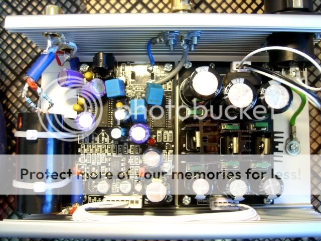
    Here are a few more photos of my project.


    Here is a list of the components changed so far...

    C3 Jamicon 220uf
    C18 Jamicon 220uf
    C11 3.3uf Tant
    C10 Vishay 0.1uf ERO 1837
    C7 Vishay 0.1uf ERO 1837
    C9 Vishay 0.1uf ERO 1837
    C16 Oscon 150uf
    C8 3.3uf Tant
    C12 3.3uf Tant
    C25 Oscon 150uf
    C26 Oscon 150uf
    C13 3.3uf Tant
    C41 Wima 0.1uf
    C19 Panasonic FC 2200uf
    C21 Panasonic FC 470uf
    C17 Oscon 150uf

    Bypass caps are SCR 8uf with R68 resistors
    Using standard JRC opamp and have also tried LM4562

    The output sounds a little bit veiled and lacking sparkle. The internal coax is a 50ohm cable from Maplin. I was after 75ohm to match the 75ohm socket but the chap at Maplins said it would not make any difference because the cable length was so short.

    Leo recommended keeping the transformer close to the DAC. Do you think I have mine too far?

    Can you recommend changing any of the parts to help improve the sound?

    Thanks

    Richard
    Hello again

    I have been running this for a while and the bass is still poor. I don't like a really pronounced bass but after listening to a variety of music it is obviously lacking.

    Can anyone provide a suggestion?

    Thanks

    Richard

  5. #235
    leo's Avatar
    leo is offline Circuit Junkie & DIY Room Forum Leader
    Join Date: Jan 2008

    Location: Notts UK

    Posts: 1,805

    Default

    Hi Richard,

    I still think the bass issue maybe the choice of caps fitted, ideally you need to look at the datasheet for the dac etc to see what each of the pins are for.
    The cap on the dacs CMOUT has an influence, a tant will be different to say an Oscon.
    I currently use a 5mm spaced 10uf MKT cap there, I wouldn't fit much higher than 10-22uf there

    Seriously though I'd remove most of those tants,Oscons and FC's and fit some cheap normal ESR types to start with, see how it sounds and then do changes to lower ESR parts in stages

    Also it seems you still use the original values for the differential output stage, changing the values to whats posted earlier does improve the sound , it also measures much flatter on the output

    THE CS4397 bass is reported to be light , mine sounds pretty deep and tight

  6. #236
    Join Date: Sep 2008

    Posts: 6

    Default

    So....without any warning my DAC started buzzing a whole ton through the outputs...the little crappy transformer that came with the DAC got VERY hot and started to melt my case.

    Any idea what could have caused this? it was working fine for over a month. Just a cheapo transformer? What kind would you recommend for a cheapish but good replacement?

    Also this morning I desoldered some bits from the PSU board to check out the components and see if I wanted to replace anything. The little green caps look very cheap and I don't know what sort of brand they are. According to the writing on the front I assume they are rated at 100V and .0035uF?

    What caps would be good replacements for these? I was looking at Wima MKP10 .022 or .033uF? Anything cheaper?

    And the big electrolytic caps are Rubycon YK for the 4700uF, and Elna RJB for the 1000uF.

    Would I benefit in changing these to something else? What would you recommend?


  7. #237
    Join Date: Sep 2008

    Location: Hampshire

    Posts: 330

    Default

    Quote Originally Posted by leo View Post
    Hi Richard,

    I still think the bass issue maybe the choice of caps fitted, ideally you need to look at the datasheet for the dac etc to see what each of the pins are for.
    The cap on the dacs CMOUT has an influence, a tant will be different to say an Oscon.
    I currently use a 5mm spaced 10uf MKT cap there, I wouldn't fit much higher than 10-22uf there

    Seriously though I'd remove most of those tants,Oscons and FC's and fit some cheap normal ESR types to start with, see how it sounds and then do changes to lower ESR parts in stages

    Also it seems you still use the original values for the differential output stage, changing the values to whats posted earlier does improve the sound , it also measures much flatter on the output

    THE CS4397 bass is reported to be light , mine sounds pretty deep and tight
    Hi Leo

    What would you recommend I remove/replace to start with?

    Do you have a list of the components/brands you have used on your board and their location?

    I really appreciate your time

    Richard

  8. #238
    leo's Avatar
    leo is offline Circuit Junkie & DIY Room Forum Leader
    Join Date: Jan 2008

    Location: Notts UK

    Posts: 1,805

    Default

    I'm not using that standard regulated psu (I just brought the dac module only) so the caps I use may not work so well with that supply you use, problem is your using a lot of low ESR caps like Oscon and Panny FC/FM which are good caps but can cause stability problems if a standard reg like LM317/337 is used, the output pin on those regs can ring with too low ESR.
    Apart from measuring worse ringing can make the sound bad too

    I mainly started the thread as it was a fun and a cheap project, the dac as standard has obvious flaws like having all its 5v and 3.3v supplies shared from a single source, the PLL filter values are wrong and so is the Differential output filter, most things can be improved though and most is covered in the thread.

    TBH I'd have changed each cap in stages and evaluated the differences, its easy to go changing a lot of parts at once but this can make things hard trying to isolate which parts are ruinning the sound


    Only thing I can recommend is taking out the Oscons,tants and replace with a decent quality general purpose type, give it a few days to run in and see how it sounds. I'd then try changing the caps in stages, this also ensures you don't go too far in the wrong direction.
    Modding this stuff to your own personal preference can be tedious but with a bit of patience usually pays off

    BTW don't always trust what you read regarding low ESR caps, their not always better in every application

  9. #239
    Join Date: Oct 2008

    Posts: 21

    Default

    Hi, I am planning to get this DAC and mod it according to the lampucera website AND the mods Leo showed. Will this have any conflicts?

    Thank you

  10. #240
    Join Date: Sep 2008

    Location: Hampshire

    Posts: 330

    Default

    Quote Originally Posted by leo View Post
    I'm not using that standard regulated psu (I just brought the dac module only) so the caps I use may not work so well with that supply you use, problem is your using a lot of low ESR caps like Oscon and Panny FC/FM which are good caps but can cause stability problems if a standard reg like LM317/337 is used, the output pin on those regs can ring with too low ESR.
    Apart from measuring worse ringing can make the sound bad too

    I mainly started the thread as it was a fun and a cheap project, the dac as standard has obvious flaws like having all its 5v and 3.3v supplies shared from a single source, the PLL filter values are wrong and so is the Differential output filter, most things can be improved though and most is covered in the thread.

    TBH I'd have changed each cap in stages and evaluated the differences, its easy to go changing a lot of parts at once but this can make things hard trying to isolate which parts are ruinning the sound


    Only thing I can recommend is taking out the Oscons,tants and replace with a decent quality general purpose type, give it a few days to run in and see how it sounds. I'd then try changing the caps in stages, this also ensures you don't go too far in the wrong direction.
    Modding this stuff to your own personal preference can be tedious but with a bit of patience usually pays off

    BTW don't always trust what you read regarding low ESR caps, their not always better in every application

    I was foolish to change so many components at once. Having read the http://www.lampizator.eu/ website and and also heard a friends modded DAC I decided to go for it!

    I normally like to take things slowly and evaluate each change. I have recently built Peter Daniels Shigaclone transport with great results and wish I had taken the same approach with this project.


    Should I stick with 150uf for the Oscon replacements and 220uf for the C3 and C18? And what about the tants, should I choose a larger value than 3.3uf?

    Thanks Leo

    Richard

+ Reply to Thread
Page 24 of 47 FirstFirst ... 14222324252634 ... LastLast

Tags for this Thread

Posting Permissions

  • You may not post new threads
  • You may not post replies
  • You may not post attachments
  • You may not edit your posts
  •