+ Reply to Thread
Page 8 of 9 FirstFirst ... 6789 LastLast
Results 71 to 80 of 85

Thread: Opinions on Tribute SUTs

  1. #71
    RothwellAudio Guest

    Default

    BTW, I found this on the Miyajima Labs website:

    Numerical value of InputCoil and OutputCoil is winding amount of the coils.
    Please choose the winding amount of InputCoil suitable for the impedance of the cartridge.

    Input Coil
    80 = 2-5 Ω
    120 = 5-12 Ω
    180 = 12-30 Ω
    270 = 30-100 Ω

    Numerical value of the output coil is winding amount of the coils.
    Please choose the appropriate numerical value to decide an amplification rate.
    For example, it is the amplification of 22.2 times when a user chooses Input180 Output4000 for a cartridge of 16 Ω.
    The output impedance switch changes the impedance of the phonostage.
    The calculation methods of Impedance are as follows.

    22.2 times x 22.2 times x cartridge 16 Ω = 7,885 Ω = 7.885 kΩ

    Therefore, please choose the impedance from 8k ohm to 47k ohm.

    In the case of MM cartridge, please choose PASS as both InputCoil and OutputCoil.
    In addition, please choose 47kΩ(PASS) as Impedance basically.


    There's some worrying stuff there, but I haven't got time to go into it all now. I'll come back to it.

  2. #72
    Join Date: Jan 2009

    Location: Norwich

    Posts: 2,814
    I'm Hugo.

    Default

    That is for the ETR-Stereo SUT with multiple gain and loading adjustments. On the other hand, the Miyajima ETR-KSW stereo SUT is simply designed for their stereo cartridges.

  3. #73
    Join Date: Jan 2009

    Location: Essex

    Posts: 32,034
    I'm openingabottleofwine.

    Default

    Quote Originally Posted by RothwellAudio View Post
    BTW, I found this on the Miyajima Labs website:

    Numerical value of InputCoil and OutputCoil is winding amount of the coils.
    Please choose the winding amount of InputCoil suitable for the impedance of the cartridge.

    Input Coil
    80 = 2-5 Ω
    120 = 5-12 Ω
    180 = 12-30 Ω
    270 = 30-100 Ω

    Numerical value of the output coil is winding amount of the coils.
    Please choose the appropriate numerical value to decide an amplification rate.
    For example, it is the amplification of 22.2 times when a user chooses Input180 Output4000 for a cartridge of 16 Ω.
    The output impedance switch changes the impedance of the phonostage.
    The calculation methods of Impedance are as follows.

    22.2 times x 22.2 times x cartridge 16 Ω = 7,885 Ω = 7.885 kΩ

    Therefore, please choose the impedance from 8k ohm to 47k ohm.

    In the case of MM cartridge, please choose PASS as both InputCoil and OutputCoil.
    In addition, please choose 47kΩ(PASS) as Impedance basically.


    There's some worrying stuff there, but I haven't got time to go into it all now. I'll come back to it.
    Reads like badly-translated Japanese: I don't quite know what they are talking about.
    Barry

  4. #74
    Join Date: Dec 2015

    Location: Alicante. Spain.

    Posts: 1,885
    I'm Adrian.

    Default

    It is badly translated Japanese lol. I would love to edit their website!
    Adey

    In perpetual pursuit.
    Technics SP10 mk2
    Jan Allaerts MC 1 Boron mk1 cart
    Miyajima Shilabe cart
    Hashimoto HM-X SUT
    Siggwan (gimballed not unipivot) Cocobola 12"
    Aurorasound Vida LCR Phonostage
    The Truth linestage
    Dave Slagle Autoformer Volume Controller
    Cary 805c SET amps
    Audio Note ANe-SPX speakers
    Townshend Isolda speaker cables
    Cardas Golden Presence interconnects

  5. #75
    RothwellAudio Guest

    Default

    Apologies if this post is a bit long but I'd like to state some engineering facts and dispel some myths.
    Firstly, cartridge loading.
    It's rare to see a cartridge manufacturer state a specific load requirement for their cartridges. Sometimes a wide range is specified but more commonly a lower limit is specified. So what effect do different loads have? If we assume the cartridge's coil to be a pure resistance the only effect the load has is to act in conjunction with the source impedance and form a potential divider which attenuates the signal. It does not alter the frequency response. In reality the cartridge's coils will have some inductance and a more sophisticated analysis will take that into account. However, the inductance is so small that it affects only ultrasonic frequencies and the simple potential divider effects of the load still apply in the audio band. So what should the load impedance be? The rule of thumb is that the load impedance should be ten times the source impedance because that results in attenuating the signal by less than 1dB. A higher load impedance will attenuate the signal even less than that, but 1dB is normally considered an acceptable loss. For comparison a load impedance equal to the source impedance will produce a 6dB loss and a load impedance three times the source impedance will produce a 2.5dB loss.

    How should the load be applied? The answer is quite simple: put it in across the source. You would think that is obvious and needs no more explanation. That's the way it is done in all active circuits and no-one questions it, but when it comes to using a step-up transformer a myth has appeared that the load should not be across the source but should be across the output of the transformer, ie in parallel with the transformer's secondary winding. Why? Although there are many websites advocating the use of a resistive load in parallel with the secondary winding of a step-up transformer there is never any explanation given as to why the load should be there. The truth is that it need not be there and should not be there if the aim is to load the cartridge. It may be true that a load on the secondary side of a transformer has a loading effect on the cartridge, but it has a loading effect on the transformer too and combining the the two effects into one only complicates things and makes it impossible to deal with the two loading effects independently.

    What are the effects of loading the transformer? A resistive load on the secondary of a step-up transformer damps high frequency ringing, but it also affects the load seen by the cartridge and causes more energy to be passed through the transformer core in the same way more energy is passed through the core of a mains transformer when a greater load is placed on it. Surely no-one would would entertain the idea of dropping a mains transformer's output by loading it excessively, yet a similar thing happens when attempting to load an MC step-up transformer with a resistive load. If the aim is to control high frequency ringing a much better way is to use a snubber network. This isn't an unknown technique in the wider world of audio and its use can be seen in microphone preamps and elsewhere. It's also common for transformer manufacturers to specify a snubber network for use with their audio transformers. For some strange reason the technique seems to have eluded most of the suppliers of audiophile LOMC step-up transformers.
    A resistive load on the secondary can have the effect of producing more bass but it's really a case of attenuating the mid and high frequencies rather than increasing the bass and again it's an effect on the transformer rather than effect on the cartridge itself.

    The Miyajima Labs ETR-Stereo transformer:
    Looking at this step-up transformer specifically, it has a facility for adding capacitance across its input with the claim that the capacitance will roll-off the cartridge's high frequencies. In reality the capacitance will produce a resonant peak before roll-off and I would advise against applying a capacitance load to a cartridge.
    The transformer also has a selector switch for choosing the number of turns of wire on primary and another for choosing the number of turns on the secondary. This allows turns ratios between 1:3.7 and 1:100 to be chosen. That's a very wide range and suggests that the unit is not designed specifically as the ideal partner for Miyajima cartridges but an attempt to accommodate all cartridges available anywhere. However, I'd estimate that 80% of the cartridges on the market don't need anything above 1:20 or anything below 1:10.
    Finally, the unit has a switch to select different resistive loads for the transformer's secondary winding. As explained above, resistive loading of the transformer is not a good idea and not a clever way to load a cartridge.
    For these reasons and the fact that absolutely no performance specifications are given, I do not think the Miyajima Labs ETR-Stereo is designed specifically for their cartridges and its design does not inspire confidence in me.

    So what would I recommend for a cartridge with a 16 ohm source impedance and an output of 0.24mV? In general terms rather than any specific manufacturer's offering, I would recommend a transformer with a turns ratio in the range 1:10 to 1:20. A turns ratio of 1:10 would yield an output of 2.3mV and a load impedance of 470 ohms. A 1:20 turns ratio would yield an output of 4.2mV and a load impedance of 117 ohms. If a lower load impedance is preferred for whatever reason I would advocate using load resistors on the primary side of the transformer - not the secondary - bearing in mind that an extra load will reduce the signal voltage into the MM phonostage.
    If the absolute maximum voltage from the transformer is required the optimum turns ratio would be 1:54 and would yield a voltage of 6.5mV. However, higher turns ratios usually result in less bandwidth and more ringing and I seriously doubt there would be any real benefit in aiming for maximum voltage rather than maximum fidelity. Personally I would choose a ratio of 1:20.

    BTW, Ammonite Acoustics has pointed out that the ETR-Stereo isn't designed specifically for Miyajima cartridges, but others in the range are.

  6. #76
    Join Date: Oct 2012

    Location: NE England

    Posts: 4,173
    I'm Jez.

    Default

    Quote Originally Posted by RothwellAudio View Post
    Apologies if this post is a bit long but I'd like to state some engineering facts and dispel some myths.
    Firstly, cartridge loading.
    It's rare to see a cartridge manufacturer state a specific load requirement for their cartridges. Sometimes a wide range is specified but more commonly a lower limit is specified. So what effect do different loads have? If we assume the cartridge's coil to be a pure resistance the only effect the load has is to act in conjunction with the source impedance and form a potential divider which attenuates the signal. It does not alter the frequency response. In reality the cartridge's coils will have some inductance and a more sophisticated analysis will take that into account. However, the inductance is so small that it affects only ultrasonic frequencies and the simple potential divider effects of the load still apply in the audio band. So what should the load impedance be? The rule of thumb is that the load impedance should be ten times the source impedance because that results in attenuating the signal by less than 1dB. A higher load impedance will attenuate the signal even less than that, but 1dB is normally considered an acceptable loss. For comparison a load impedance equal to the source impedance will produce a 6dB loss and a load impedance three times the source impedance will produce a 2.5dB loss.

    How should the load be applied? The answer is quite simple: put it in across the source. You would think that is obvious and needs no more explanation. That's the way it is done in all active circuits and no-one questions it, but when it comes to using a step-up transformer a myth has appeared that the load should not be across the source but should be across the output of the transformer, ie in parallel with the transformer's secondary winding. Why? Although there are many websites advocating the use of a resistive load in parallel with the secondary winding of a step-up transformer there is never any explanation given as to why the load should be there. The truth is that it need not be there and should not be there if the aim is to load the cartridge. It may be true that a load on the secondary side of a transformer has a loading effect on the cartridge, but it has a loading effect on the transformer too and combining the the two effects into one only complicates things and makes it impossible to deal with the two loading effects independently.

    What are the effects of loading the transformer? A resistive load on the secondary of a step-up transformer damps high frequency ringing, but it also affects the load seen by the cartridge and causes more energy to be passed through the transformer core in the same way more energy is passed through the core of a mains transformer when a greater load is placed on it. Surely no-one would would entertain the idea of dropping a mains transformer's output by loading it excessively, yet a similar thing happens when attempting to load an MC step-up transformer with a resistive load. If the aim is to control high frequency ringing a much better way is to use a snubber network. This isn't an unknown technique in the wider world of audio and its use can be seen in microphone preamps and elsewhere. It's also common for transformer manufacturers to specify a snubber network for use with their audio transformers. For some strange reason the technique seems to have eluded most of the suppliers of audiophile LOMC step-up transformers.
    A resistive load on the secondary can have the effect of producing more bass but it's really a case of attenuating the mid and high frequencies rather than increasing the bass and again it's an effect on the transformer rather than effect on the cartridge itself.

    The Miyajima Labs ETR-Stereo transformer:
    Looking at this step-up transformer specifically, it has a facility for adding capacitance across its input with the claim that the capacitance will roll-off the cartridge's high frequencies. In reality the capacitance will produce a resonant peak before roll-off and I would advise against applying a capacitance load to a cartridge.
    The transformer also has a selector switch for choosing the number of turns of wire on primary and another for choosing the number of turns on the secondary. This allows turns ratios between 1:3.7 and 1:100 to be chosen. That's a very wide range and suggests that the unit is not designed specifically as the ideal partner for Miyajima cartridges but an attempt to accommodate all cartridges available anywhere. However, I'd estimate that 80% of the cartridges on the market don't need anything above 1:20 or anything below 1:10.
    Finally, the unit has a switch to select different resistive loads for the transformer's secondary winding. As explained above, resistive loading of the transformer is not a good idea and not a clever way to load a cartridge.
    For these reasons and the fact that absolutely no performance specifications are given, I do not think the Miyajima Labs ETR-Stereo is designed specifically for their cartridges and its design does not inspire confidence in me.

    So what would I recommend for a cartridge with a 16 ohm source impedance and an output of 0.24mV? In general terms rather than any specific manufacturer's offering, I would recommend a transformer with a turns ratio in the range 1:10 to 1:20. A turns ratio of 1:10 would yield an output of 2.3mV and a load impedance of 470 ohms. A 1:20 turns ratio would yield an output of 4.2mV and a load impedance of 117 ohms. If a lower load impedance is preferred for whatever reason I would advocate using load resistors on the primary side of the transformer - not the secondary - bearing in mind that an extra load will reduce the signal voltage into the MM phonostage.
    If the absolute maximum voltage from the transformer is required the optimum turns ratio would be 1:54 and would yield a voltage of 6.5mV. However, higher turns ratios usually result in less bandwidth and more ringing and I seriously doubt there would be any real benefit in aiming for maximum voltage rather than maximum fidelity. Personally I would choose a ratio of 1:20.

    BTW, Ammonite Acoustics has pointed out that the ETR-Stereo isn't designed specifically for Miyajima cartridges, but others in the range are.
    "careful now", "down with that sort of thing"

    Good post
    Arkless Electronics-Engineered to be better. Tel. 01670 530674 (after 1pm)

    Modded Thorens TD150, Audio Technica AT-1005 MkII, Technics EPC-300MC, Arkless Hybrid MC phono stage, Arkless passive pre, Arkless 50WPC Class A SS power amp, (or) Arkless modded Leak Stereo 20, Modded Kef Reference 105/3's
    ReVox PR99, Studer B62, Ferrograph Series 7, Tandberg TCD440, Hitachi FT-5500MkI, also FT-5500MkII
    Digital: Yamaha CDR-HD1500 (Digital Swiss army knife-CD recorder, player, hard drive, DAC and ADC in one), PC files via 24/96 sound card and SPDIF, modded Philips CD850, modded Philips CD104, modded DPA Little Bit DAC. Sennheiser HD580 cans with Arkless Headphone amp.
    Cables- free interconnects that come with CD players, mains leads from B&Q, dead kettles etc, extension leads from Tesco

  7. #77
    Join Date: Dec 2015

    Location: Alicante. Spain.

    Posts: 1,885
    I'm Adrian.

    Default

    Thanks for that Dave (hope I've got your name right). I wouldn't go for the Miyajima you're discussing - my interest is in the KSW which is specifically for the Shilabe and Kansui, or the best quality at 1:10/1:20


    Adey

    In perpetual pursuit.
    Technics SP10 mk2
    Jan Allaerts MC 1 Boron mk1 cart
    Miyajima Shilabe cart
    Hashimoto HM-X SUT
    Siggwan (gimballed not unipivot) Cocobola 12"
    Aurorasound Vida LCR Phonostage
    The Truth linestage
    Dave Slagle Autoformer Volume Controller
    Cary 805c SET amps
    Audio Note ANe-SPX speakers
    Townshend Isolda speaker cables
    Cardas Golden Presence interconnects

  8. #78
    Join Date: Sep 2010

    Location: Nr Ashbourne, East Midlands, UK

    Posts: 110
    I'm Mike.

    Default

    Cut and pasted from my emails with Noriyuki Miyajima

    '16 Ω of ETR-KSW writing in the website is real input impedance. (phonostage of the 47k load)
    I produced many stepup transformers, but found that I could not make a good sound only at the ratio.
    The ratio and coil width and the number of times and the materials have a big influence on sound quality.
    I produced a large number of stepup transformers to look for the stepup transformer which was most suitable for a cartridge of Miyajima-lab.
    The stepup transformer which gave my ideal sound quality is ETR-KSW.
    ETR-KSW is suitable for all cartridges of Miyajima-lab.'
    StSt Motus DQ + SME 312 'MB Special'
    Transfix Axia / HM7
    Art Audio Vinyl 1 Ref
    Modified Mac Mini/Weiss DAC 202
    SJS Model 2
    BP P20 (SJS upgraded)
    Trenner and Friedl RA
    [/SIZE]

  9. #79
    Join Date: Dec 2015

    Location: Alicante. Spain.

    Posts: 1,885
    I'm Adrian.

    Default

    Thanks Mike. I'm hoping to go the KSW route, and your input is invaluable.

    Adey

    In perpetual pursuit.
    Technics SP10 mk2
    Jan Allaerts MC 1 Boron mk1 cart
    Miyajima Shilabe cart
    Hashimoto HM-X SUT
    Siggwan (gimballed not unipivot) Cocobola 12"
    Aurorasound Vida LCR Phonostage
    The Truth linestage
    Dave Slagle Autoformer Volume Controller
    Cary 805c SET amps
    Audio Note ANe-SPX speakers
    Townshend Isolda speaker cables
    Cardas Golden Presence interconnects

  10. #80
    Join Date: Dec 2015

    Location: Alicante. Spain.

    Posts: 1,885
    I'm Adrian.

    Default

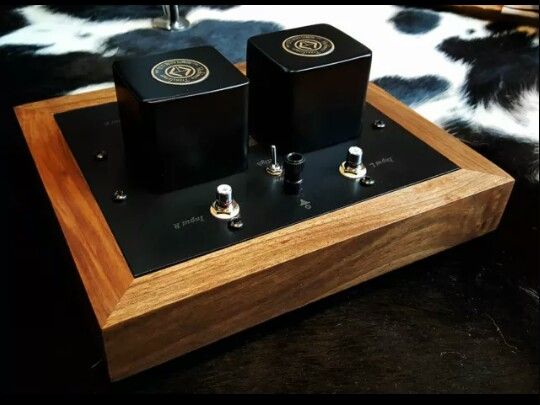
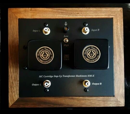
    Update. I've just bought this HM-X Hashimoto SUT from fellow member nestor. It marks, I'm sure, the beginning of my SUT/head amp adventure and am looking forward to hearing it - Spanish customs withstanding!

    The HM-X is just below the HM-7 in price, and shares the same ratios. They have a different response being 15hz-100khz versus 10hz-80khz but I've high hopes of them.

    Will report.


    In perpetual pursuit.
    Technics SP10 mk2
    Jan Allaerts MC 1 Boron mk1 cart
    Miyajima Shilabe cart
    Hashimoto HM-X SUT
    Siggwan (gimballed not unipivot) Cocobola 12"
    Aurorasound Vida LCR Phonostage
    The Truth linestage
    Dave Slagle Autoformer Volume Controller
    Cary 805c SET amps
    Audio Note ANe-SPX speakers
    Townshend Isolda speaker cables
    Cardas Golden Presence interconnects

+ Reply to Thread
Page 8 of 9 FirstFirst ... 6789 LastLast

Posting Permissions

  • You may not post new threads
  • You may not post replies
  • You may not post attachments
  • You may not edit your posts
  •