+ Reply to Thread
Page 1 of 10 123 ... LastLast
Results 1 to 10 of 96

Thread: How to Connect an External Dc Supply to the SL-1200/1210

  1. #1
    Join Date: Jan 2009

    Location: Norwich

    Posts: 2,814
    I'm Hugo.

    Default How to Connect an External Dc Supply to the SL-1200/1210

    INSTALLING AN EXTERNAL REGULATED DC SUPPLY IN THE TECHNICS SL-1200/1210

    1. Remove the platter mat, and pull the platter upwards, using the two holes to get a firm hold. The large plastic cover must now be removed, by undoing the 5 small screws around the edge:


    2. When the cover is removed, this is what you see:


    The mains cable enters at the top from underneath the turntable, through a clamping gland, then it goes to the small power PCB that you can see on the left below the transformer. The first job is to remove the old mains cable:


    a. Undo the small metal plate that holds the cable gland. Squeeze the underside of the cable gland using a pair of pliers, and push it upwards. The gland can be easily removed now.


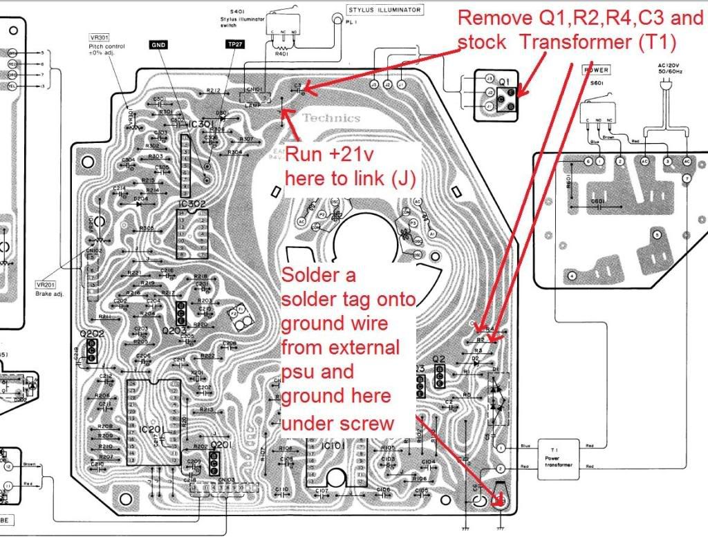
    b. Snip the light blue and brown AC cables from the small power PCB, just above the fuse, as seen in the picture below:


    c. Release the mains cable, threading it through the bottom of the chassis. You don’t need this cable any more, unless you wish to reinstate the deck to standard fettle.


    d. At this point, you can, if you wish, remove the entire mains transformer and power PCB assembly. Doing so is said to further improve sound quality. If you want to do this, carefully snip (close to the PCB) the light blue, dark blue and brown wires from the power PCB points marked “SW”. Tidy these 3 wires to one side. Then snip the small red and blue wires from the bottom left hand corner of the main control board (next to the large electrolytic capacitor). Remove the 3 small black screws from the top of the mains transformer and remove the metal screen – you can now undo the 3 securing screws holding it to the chassis. Undo the two silver screws holding the power PCB to the chassis, and then the whole assembly can be lifted away.

    3. Thread your new DC power cable through the bottom of the chassis and through the small metal plate. Don’t secure it with the cable gland just yet.

    4. You now need to remove the Technics 3-pin regulator device, which is located above the main control PCB, next to where the power cable enters. It has 3 wires (red, yellow, orange) which go to the main PCB (marked “J1”, “J2” and “J3”). Snip the wires as shown below:


    You can leave the device in-situ, or remove it – it’s your choice.

    5. Now take enough of your incoming DC cable to allow the NEGATIVE wire to thread neatly to the bottom left hand corner of the main control PCB. Attach a small circular solder tag to the end, and secure it to the main PCB earth point at the bottom left corner of the PCB, using the existing screw and serrated washer. See how the black wire in the picture below is routed to the left of the PCB, and secured:


    6. Take the POSITIVE wire and shorten it, so that reaches the PCB, as shown by the white wire in the pictures above and below. Strip and tin the end, and solder it to the wire link on the PCB (just to the left of the word “LAMP”) as shown below:


    7. Double-check your PSU polarity, and that it’s giving 21v DC. Test that everything’s OK by replacing the platter (don’t worry about the plastic cover for this testing). Plug your DC lead into the PSU in and turn it on. The red strobe light should be illuminated all the time, irrespective of the position of the on/off switch. Press the start/stop button and the platter should spin up and stabilise. If all is well, remove the platter, replace the plastic cover, put the platter back on again, and that’s it!

    8. If you are bothered about not having a working power switch on your deck, it’s not much trouble to take the blue and brown wires that you may have snipped in Step 2d, and route your positive DC lead through the deck’s power switch, using these existing wires. You’ll have to work out which ones to use with the aid of a multimeter, but that’s not difficult! Then your deck will operate exactly as before.

  2. #2
    Join Date: Jun 2009

    Location: Berkshire uk

    Posts: 1,745
    I'm Allthatwasisorwillbe.

    Default

    hi hugo,

    thanks for walk through much needed,i have a couple of questions though.

    If i follow your instructions and solder the dc cable as you say, on the plug end where would the + and - go? would the outer small tab be +?

    On my power pcb board there is a yellow and bue cable which goes to the main pcb marked AC,i assume i cut these two?

    The only cables left attached to the power pcb board are thick brown blue and red ones which i assume are connected to the on/off switch which i cut yes?

    Sorry for being dumb here but it looks like i have a couple of different coloured cables and i can't see any points marked sw.
    Last edited by kininigin; 21-10-2010 at 15:17.
    Darren

    KORUS CUSTOM SERVER
    TECHNICS 1200 MKII_JELCO 750D_SHURE SC35C (with NOS and NEO SAS styli)
    CAIMAN SEG + DORADO PSU
    CROFT MEGA MICRO
    PARADIGM REFERENCE ACTIVE/40'S
    PARADIGM SERVO 15 SUBWOOFER X 2


    ''The theory of relativity is a mass of error and deceptive ideas violently opposed to the teachings of great men of science of the past and even to common sense''

  3. #3
    Join Date: Jun 2009

    Location: Berkshire uk

    Posts: 1,745
    I'm Allthatwasisorwillbe.

    Default

    Quote Originally Posted by kininigin View Post
    hi hugo,


    If i follow your instructions and solder the dc cable as you say, on the plug end where would the + and - go? would the outer small tab be +?

    .
    I sussed out the removal of the old psu just need the answer to this question
    Last edited by kininigin; 21-10-2010 at 15:16.
    Darren

    KORUS CUSTOM SERVER
    TECHNICS 1200 MKII_JELCO 750D_SHURE SC35C (with NOS and NEO SAS styli)
    CAIMAN SEG + DORADO PSU
    CROFT MEGA MICRO
    PARADIGM REFERENCE ACTIVE/40'S
    PARADIGM SERVO 15 SUBWOOFER X 2


    ''The theory of relativity is a mass of error and deceptive ideas violently opposed to the teachings of great men of science of the past and even to common sense''

  4. #4
    Join Date: Jun 2009

    Location: Berkshire uk

    Posts: 1,745
    I'm Allthatwasisorwillbe.

    Default

    anyone?
    Darren

    KORUS CUSTOM SERVER
    TECHNICS 1200 MKII_JELCO 750D_SHURE SC35C (with NOS and NEO SAS styli)
    CAIMAN SEG + DORADO PSU
    CROFT MEGA MICRO
    PARADIGM REFERENCE ACTIVE/40'S
    PARADIGM SERVO 15 SUBWOOFER X 2


    ''The theory of relativity is a mass of error and deceptive ideas violently opposed to the teachings of great men of science of the past and even to common sense''

  5. #5
    Join Date: Jan 2009

    Location: Norwich

    Posts: 2,814
    I'm Hugo.

    Default

    Quote Originally Posted by kininigin View Post
    I sussed out the removal of the old psu just need the answer to this question
    It is usual, but not universal, for the DC+ to be the centre pin of a circular DC power connector, and I believe that's the case on the Timestep, but do check with a multimeter and be quite sure. There is no right or wrong here - as long as you know which way round the +ve and -ve go in your PSU and connect the deck up to the DC connector correctly, then all will be well.

  6. #6
    Join Date: Dec 2008

    Location: So Cal

    Posts: 139
    I'm Pete.

    Default

    Great post Shuggie!

    You might also consider removing C4, R2 and R4 for completeness.

    Here is pic from a post about Technics external powersupplies, on audiocircle in the Paul Hynes' section

    Hearing is believing

    SL-1210 Mk5 w/Mike New Platter/bearing/armboard; Hynes SR5 DIY PSU;
    Zyx Airy3X; SME V; Hashimoto HM7 SUT; CJ PR15MkII Phono w/teflon caps.

    Modwright LS36.5 Dual Mono Preamp & KWA 150 amp > Paradigm Ref 100 v.4s

  7. #7
    Join Date: Dec 2008

    Location: So Cal

    Posts: 139
    I'm Pete.

    Default

    oops! double post...
    Hearing is believing

    SL-1210 Mk5 w/Mike New Platter/bearing/armboard; Hynes SR5 DIY PSU;
    Zyx Airy3X; SME V; Hashimoto HM7 SUT; CJ PR15MkII Phono w/teflon caps.

    Modwright LS36.5 Dual Mono Preamp & KWA 150 amp > Paradigm Ref 100 v.4s

  8. #8
    Join Date: Aug 2009

    Location: West Yorkshire

    Posts: 1,796
    I'm Stephen.

    Default wiring if you want to keep the switch

    I am one of those who likes the power switch to work so have kept it in the circuit. In my case it was the brown and blue wires at bottom of the power pcb that went to and from the power switch - the third wire (in my case red not light blue) was not involved. The photo shows the wiring - heat shrink keeps the joins tidy and I then used a dab of hot glue to keep the wires in place (not shown).
    IMHO I could not detect any degradation in sound with the switch in or out of the circuit.

    Steve
    Attached Images Attached Images

  9. #9
    Mike_New Guest

    Default

    Pete,
    I believe it would be unwise to remove the C3 or C4 in the context of the TimeStep power supply; as this is a capacitor which sits across the 21V supply to the main power feed to the motor drive circuit IC and also to the stator coils themselves!
    In fact I have increased the value of this cap to 100uF using a quality Alluminium foil type. The 21V also of course has to feed other elements of the circuit, but in many cases these are stepdown voltages via further regulators; which I believe the super duper Paul Heynes power supply addresses.
    The Timestep power supply does have a reasonable 4700uF across the rectifier bridge output, before the LM317 regulator. However the capacitor across the output DC is a modest 100uF.
    If one wish’s to improve the PS further then they should look at replacing the rather loose and ineffective co-axial connector, the possible intermittent contact resistance at this point could cause a loss of integrity of DC supply.
    In fact I consider the best connector is no connector!!
    Directly connect the DC into the SL1200 with a better quality twin cable.

  10. #10
    Join Date: Dec 2008

    Location: So Cal

    Posts: 139
    I'm Pete.

    Default

    Good points Mike. I have a Hynes SR5 DIY psu, so I followed the diagram I posted above.
    Hearing is believing

    SL-1210 Mk5 w/Mike New Platter/bearing/armboard; Hynes SR5 DIY PSU;
    Zyx Airy3X; SME V; Hashimoto HM7 SUT; CJ PR15MkII Phono w/teflon caps.

    Modwright LS36.5 Dual Mono Preamp & KWA 150 amp > Paradigm Ref 100 v.4s

+ Reply to Thread
Page 1 of 10 123 ... LastLast

Posting Permissions

  • You may not post new threads
  • You may not post replies
  • You may not post attachments
  • You may not edit your posts
  •