Hi Folks,
If this works we should have a picture of the internals of my Bearing which I do not think I have ever shown in detail before.
I have not done so before as I did not particularly want to make it any easier for those who would want to copy my rather unique design.
However at this stage I feel I should give others a chance!!
I will provide a detailed description so that the value of the Bearing can be appreciated:
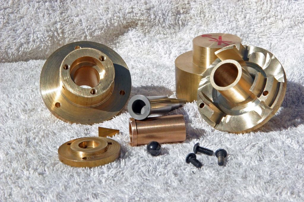
a) The large left hand component is the rear or bottom base of the Bearing
b) The thin brass plate is the bottom support attached by the 3 4mm tensile bolts shown in the foreground
c) The triangular component is the coated carbide thrust pad which supports the Ball.
d) The black ball in the center of the assembly is of course the 3/8" precision Silicone Nitride Ball
This ball is fully floating inside the main shaft, and is located at the bottom of the shaft.
The 13.5mm dia. main shaft itself can be seen resting on the Syntered Oilite lateral bearing insert.
Note the counter bored hole to occomodate the thrust ball. The diameter of this hole is precisely fixed to allow the
smallest amount of lateral play and to provide the circulation of the special oil.
e) The cylindrical component with the flange at the left hand side and just behind the ball is the Syntered Phosphor Bronze
Oilite bearing insert.
f) The complex machined component at the top right of the picture is the main Bearing Housing. Machned from a solid
brass bar. Note the large rigid center column which occomodates the syntered bearing.
The Syntered bearing insert is a heat shrink and force fit into the housing to producing the maximum rigidity from the assembly.
When the inserts have been installed into the Bearings I then send them to my Toolmakers who precision hone each bearing insert
individually to fit the shafts which they have previously made, with a clearance measured in microns.
The shafts are precision machined from M22 carbon steel before hardening and Nitriding.
They are then polished to a surface finish of a few microns.
The whole object of my Bearing design some 6 years ago now; was to optimise the limited volumetric space available.
And to provide a Bearing with the maximum length and diameter possible. This I believe I have done.
When the honed and fitted shafts are returned to me I then machine the bottom plate for each bearing so that the Taper
is set to a standard position/height according to a master gauge.
The base plate, carbide pad and ball must be assembled for this procedure.
When all Bearings have been assembled and the end plates bolted and sealed with Loktite, the bottom base of the
Bearing is then filled with sythetic oil and sealed.
You can see the hole in the base through which I use a hyperdermic needle to feed the oil.
This hole is then sealed with a brass pin and the whole back end is then finish machined.
The whole design centres around the extremely high precision polished shaft which provides for exceptionally smooth
yet firm rotation. Something nobody else has has been able to achieve with all the variations which come and go.
I guess it would be evident to the reader by now, why these Bearings are the standard by which all the other offerings are measured
in both engineering quality and sonics which is the most important consideration.


 Reply With Quote
 Originally Posted by Ants

 Damn well nailed that shut.
