


As bought from here:
http://www.ebay.co.uk/itm/2917862715...%3AMEBIDX%3AIT
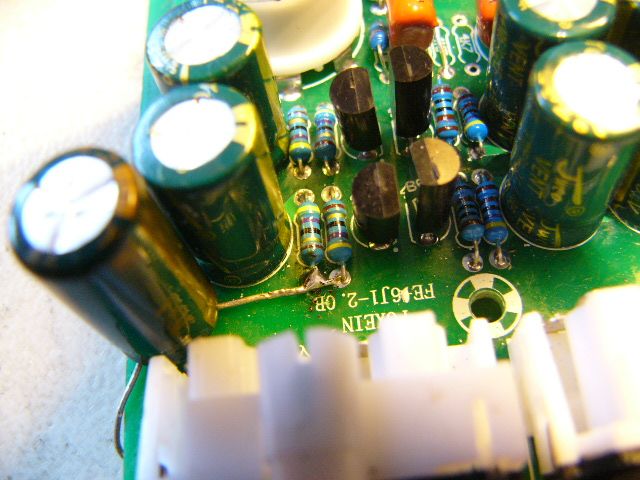
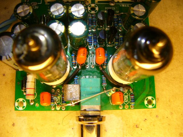
As standard there is a low level hum present, this is cured by fitting an extra capacitor. You need a 470uF 35V electrolytic, the NEGATIVE lead is connected to the junction of two 47 ohm resistors on the top of the board as shown below:
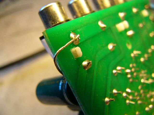
The POSITIVE lead is wrapped around the side of the board and connected to the 0V or 'earth' connection of the input sockets:
Modification to covert to a buffer stage.
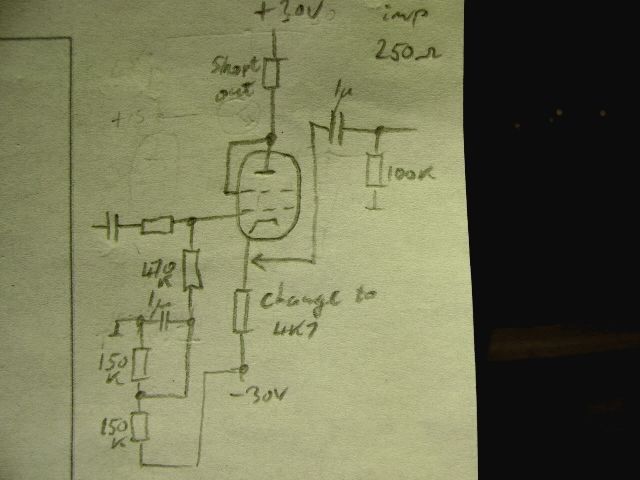
The circuit of the board is this:
...although the 100K output resistors are actually connected to 0V not -28V as shown.
To alter the function from a gain pre-amp to a zero gain buffer stage the circuit is altered so:
Three new components need to be added to give the correct valve biasing. 2x 150K resistors and a 1uF decoupling capacitor.
The two 4.7K anode load resistors are removed from the centre of the board and replaced with wire links:
Replace the two 220 ohm cathode resistors with the two 4.7K resistors just removed.
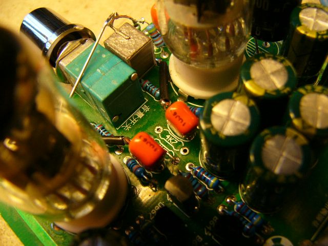
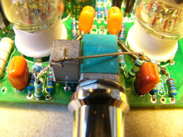
The two 1uF output capacitors have the front leads lifted from the board (closest to the volume control), then extended and connected to pin 2 of each valve, shown below:
The extra biasing components are fitted to the front of the board once the two 470K grid resistors also have their front leads lifted from the pcb.
The connecting points can be seen in this photo:
Job done

 Reply With Quote

 Originally Posted by nthall

 .... ؠ ......