Hi Sam
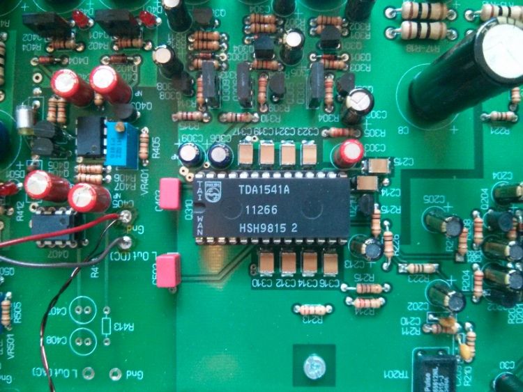
There is some optimization of this area, Philips originally fitted 100n ( 104) caps all SMD
but are capacitors the best part ?, or a part they found would work in place of doing more
research ?. It would suggest either bipolar transistors, or even fets may be better. I have
many years ago tried diodes, but now have much better skill with SMD parts. The
description below is quite complex ( as you can see ) and has far too many
dependencies on other circuitry, being added , but not necessarily related to the DAC itself,
for my liking. Needs a bit more research,
Cheers / Chris
http://www.dutchaudioclassics.nl/philips-tda1541.asp
To switch the binary weighted currents to the output line of the D/A converter, three different types of switches are used depending on the value of the bit currents to be switched. To avoid differences in base current losses owing to the different bit currents, the six most significant bits are switched with a fast diode-transistor switch, as is shown in Fig. 4. The diode-transistor switch is controlled by data latches and driven by a differential amplifier. At the emitter node of the switch a voltage swing of half the collector swing is present. To avoid long settling times due to the parasitic load Zout, a cascode stage is added. To further minimize this parasitic load and to preserve the current generation network from switching transients, an extra cascode stage is added. The next four bit currents are switched with compensated diode-transistor switches, as shown in Fig. 5. This compensation is added to cancel the voltage swing at the current source connection which causes long settling times as these bit currents are small to discharge the parasitic capacitors. When the bit current is drained to Vref, an extra current Icomp is added to the current source connection and this causes an extra voltage drop over the resistor R, which cancels the voltage swing at the emitter node. Furthermore, a cascode stage is added to minimize the influence of the remaining voltage swing across the parasitic load, which is mainly the collectorsubstrate capacitance of the passive divider.


Listening to my modded CD40 atm, done the NOS wiring but not sure how to solder the 14 decouping caps on the TDA1541A? do i desolder (remove a little solder first) on the smd or just solder it to the top of the smd?
nice bass and detail


 Reply With Quote
 Originally Posted by Light Dependant Resistor