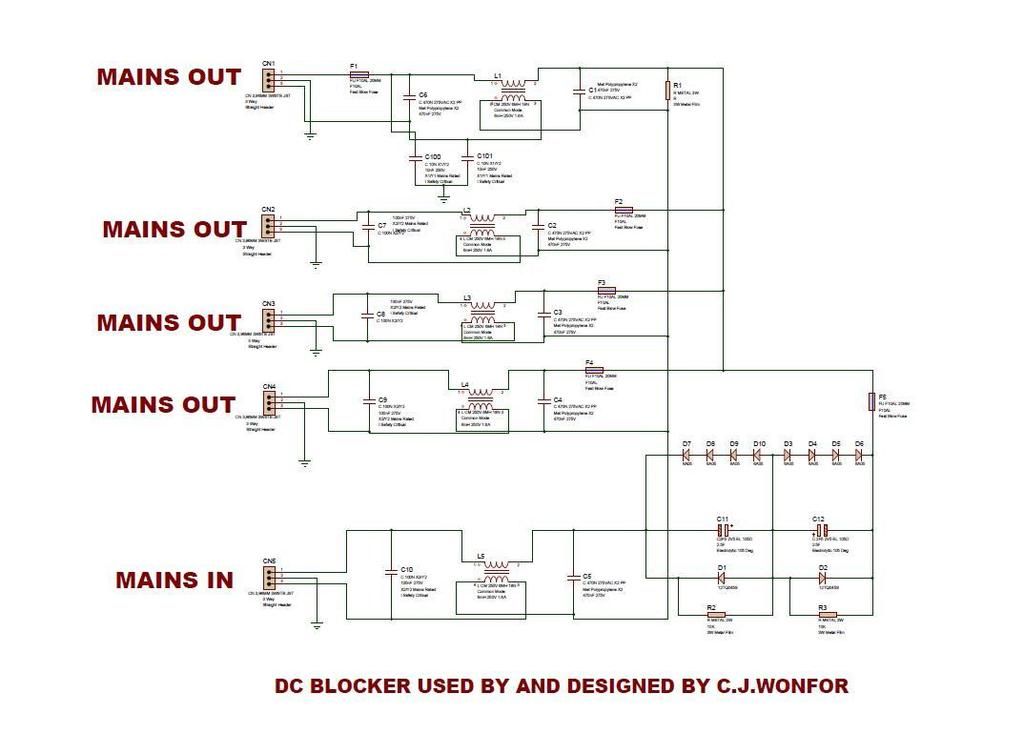
The Sjöström DC blocker uses 6 diodes, rather than 4. I've no idea if 6 diodes means a better circuit.Originally Posted by sq225917


 Trade: Ammonite Acoustics

Location: Norwich
Posts: 2,814
I'm Hugo.
The Sjöström DC blocker uses 6 diodes, rather than 4. I've no idea if 6 diodes means a better circuit.
Trade: Ammonite Acoustics
Location: Norwich
Posts: 2,814
I'm Hugo.
Maybe it's just me, but every mains filtration device that I've heard which uses series chokes has a negative effect on musical replay. I know that designs involving series chokes are technically more 'effective' at cleaning up mains crud than simpler parallel filters, but until someone shows me otherwise, I reckon that they throw too many babies out with the proverbial bathwater. What's the general view here?
New Member
Location: London UK
Posts: 28
I'm Carlos.
Thanks for your advice Barry.
I have a question about where to place these DC Blockers.
Would they be connected just before the amplifier?
OR
Would they be placed before a device that might be 'leaking DC' back into the AC supply?
OR
Is my question silly?
thanks (got a really bad headache today - I'm really not thinking clearly today)
I'm not an electric type guy, so this is my silliest question (today): How would one safely measure if there is DC leaking?
I had the silly idea that an improved DC blocker might be able to be 'switched on' only when DC is detected on the AC line, OR is the amount of 'blocking' adjustable based on the amount of DC. (If DC Blockers might be detrimental to the overall sound of an amplifier, can an improved version be switched on when needed, and the amount of 'blocking' adjusted) - Please don't laugh too hard at me
Last edited by Carlos-UK-2016; 26-03-2016 at 14:04.
Senior Member
Location: Toulouse, France
Posts: 6,564
I'm Kevin.
I have mine fitted just before my amplifier.
Kevin
Too busy enjoying the music....
European loan coordinator for Graham Slee HiFi system components..
New Member
Location: London UK
Posts: 28
I'm Carlos.
Thanks Kevin.
One thing that I have been searching for which might seem simple to some of you guys, is How to measure if you do have an issue with DC on your AC mains.
I found this article, which I would like to ask you guys for advice on. It suggests measuring DC using a multimeter on the speaker terminals of your amplifier.
Since I use integrated tube amp, I am worried about running the tube amp without the speakers attached (without a load).
Here is the link: http://www.wikihow.com/Measure-DC-Offset
It may be a basic question, but is this the ONLY way to measure for DC problems, or do you guys use other methods also. I would be really useful to some of the people with less experience (people like me), if you more experienced guys could give a few options of how to measure DC offset etc... so that we can see if we have issues, and so that we can see that where we might be adding DC Blockers, that the 'fix' has some concrete effect.
thanks
Senior Member
Location: Down South
Posts: 2,413
I'm Neal.
Measuring for DC on your speaker terminals won't tell you if you have DC on the mains! They are two separate measurements. A valve amp with an output transformer should not have any DC on the speaker terminals. I measured my mains using an oscilloscope. Edit, Oh you will need a capacitor and resistor filter cct to take the measurment from.
Listening in a Foo free Zone...
Only a Sith deals in absolutes.
Trade: Longdog Audio
Location: Halifax, UK
Posts: 1,399
I'm Nick.
DC on the mains supply will not cause DC on the output of a SS amplifier. The issue of DC offset from a amplifier can be a issue but is not in any way related to offset AC from the mains.
If you have a valve amplifier with output transformers, unless they do something rare there will by definition be no DC on the output terminals as you are connecting to the secondary of a transformer. Transformers will not pass DC.
Edit: Neal got there first :-)
Nick.
New Member
Location: London UK
Posts: 28
I'm Carlos.
Thanks for that info Nick & Neal, it really helps
I use an AC regenerator (AG500) that has six outputs (I believe it converts AC to DC and back to AC to clear out any DC problems). I plug in all my audio equipment to this unit for power.
I play my flac music files on a Mac Mini which has an internal SMPS, and I think it may cause problems; so I wanted to try to isolate it (the Mac Mini) from the 6 outputs from the AC regenerator, while still feeding the Mac Mini a stable 230v from the regenerator. I was hoping to put a DC Blocker before the Mac Mini so that DC doesn't cross back to the clean AC regenerator (If that makes sense?), I am not sure if that is the right option to try, any thoughts on this?
Notes: Also, plugged into the AC regenerator are: DAC & REL subwoofer & SET tube amp.
The DAC has a separate power supply & is connected to Mac Mini with USB cable. The DAC is connected to tube amp with RCA interconnects.
I have been thinking about removing the internal SMPS from the Mac Mini, and replacing it with the Uptone MMK kit (which will allow me to use a linear power supply (LPS) with the Mac Mini), but I wanted to try a DC Blocker first. Link to Mac mini DC-Conversion / Linear Fan Controller Kit (MMK): http://uptoneaudio.com/products/mac-...roller-kit-mmk
Last edited by Carlos-UK-2016; 28-03-2016 at 19:51. Reason: added notes
Senior Member
Location: Down South
Posts: 2,413
I'm Neal.
What makes you think the Mac mini is putting DC onto the mains? If you want to isolate it plug it into a separate mains socket! The regenerator will continue to filter the mains for all your other devices.
Listening in a Foo free Zone...
Only a Sith deals in absolutes.
Trade: Longdog Audio
Location: Halifax, UK
Posts: 1,399
I'm Nick.
You could make a 230v : 230v isolating transformer out of two 230v:9v 100va transformers back to back. The resulting AC will be less than the 230v in, but the SMPS will deal with that, and it will isolate any DC offset the SMPS is adding from the regenerated AC.
Nick.
 Posting Permissions
 Reply With Quote