+ Reply to Thread
Results 1 to 9 of 9

Thread: Rotary switch for input selectiion

  1. #1
    Join Date: Dec 2014

    Location: Wootton, North Lincolnshire

    Posts: 68
    I'm Chris.

    Default Rotary switch for input selectiion

    I could do with some help on this please.
    I have 2 sources, a deck+preamp on one side and a Raspberry Pi with a DAC on the other.........I may have a third later....so will wire up accordingly.
    To select I have bought a 3 way 4 pole rotary switch, 12 pins on circumference and 4, ABC &D in the centre
    I have done the continuity test and established pinouts for each of the three positions, as example, position 1 gives connections A=1 B=4 C=7 D=10, and so on.
    I understand that I use 2 of the ABCD centre pins for out put, + for left and right centre pin .
    Obviously these will correspond with the input connections for each as determined by the continuity test.
    That leaves the - signal, the connections will be RCA , so outer shell connections.
    I have looked up and read all I can find and am now hopelessly confused.........how do I connect the negative? string one connection across them? all Make each one part of a pair and switchable?
    and that`s before audio ground etc...............arguments and theories........Or is the audio ground one and the same as the negative? or are they joined? what do I ground to?
    The idea is simple, unbalanced unshielded RCA jacks using twin conductor cables, one + and one - for each port.
    The RCA females will be in a bank of 3 pairs, close to the switch so only about 100mm cable run each, and the output will be a short pair of interconnects with the switch end soldered direct.
    Any clues or guides of what to do in simple terms welcome, I have no end of guides of increasing complexity that are not much use.
    Also, it is a BTL amp, but I suspect that has no impact on input considerations...???

  2. #2
    Join Date: Aug 2012

    Location: Hartlepool UK

    Posts: 1,640
    I'm Alan.

    Default

    Does this help?

    Alan

    IMG_2376 by Alan Towell, on Flickr
    Turntable - Garrard 401/Jelco 750L/Ortofon Kontrapunkt B, Pioneer PLC 590, Micro Sieki MA505 , Denon DL103R - DIY Paradise Phono stage - Reel 2 Reel Studer A810, Otari MX55,Tascam BR20, Revox A77, B77, PR99, TEAC X1000 & 3440, Digital HTPC / Young Dac - Preamp - DIY B4, 821, Power Amp's DIY Avondale NCC300 Mono Block, Speakers Wilmslow Kit Volt BM220.8 / Scanspeak D2905/9500

  3. #3
    Join Date: Dec 2014

    Location: Wootton, North Lincolnshire

    Posts: 68
    I'm Chris.

    Default

    Alan, first, thanks for the response.
    I think I get the gist , my setup is intended to be simpler and am I right in guessing you have the 2 layer rotary as a volume control? I have thought about a volume control as well but it depends on how complicated it makes it...
    If I see it OK, the red cables to the RCA ports are the positive signal for one side (Right side? ) the blue for left. The return path via the bare cable running the length of the RCA bank connected to each.........
    ( I will have to absorb this stage by stage, very new to this level of things )
    Thanks for such a clear photo, the finished chassis suite looks superbly elegant.

    Chris

  4. #4
    Join Date: Mar 2008

    Location: Galashiels

    Posts: 13,696
    I'm inthescottishmafia.

    Default

    Yes, the ground (-ve) of the rca's is all tied together with the bare cable.
    “Music has always been a matter of energy to me, a question of fuel. Sentimental people call it inspiration, but what they really mean is fuel. I have always needed fuel. I am a serious consumer. On some nights I still believe that a car with the gas needle on empty can run about fifty more miles if you have the right music very loud on the radio”

    Hunter S Thompson

  5. #5
    Join Date: Dec 2014

    Location: Wootton, North Lincolnshire

    Posts: 68
    I'm Chris.

    Default

    Ali, Thanks...... Getting somewhere now! Final part of the puzzle is just where to "ground" the ground cabling, for the in to the switch I am using phono cables/interconnects, from the turntable and the Pi DAC, then wires from back of RCA ports to the switch, so does the ground have to find its way back to their circuitry? ( TT and Pi?)

    Ah...... The ground will be connected right through via the RCA shells all the way through......switch to RCA bank, then phono to amp (and Pi DAC) RCA which are already audio grounded /return path on each.......I think I have it now...........
    Last edited by stree; 26-02-2016 at 20:53.

  6. #6
    Join Date: Mar 2011

    Location: Preston

    Posts: 197
    I'm Paul.

    Default

    star earth it - tie every earth back to a single screw on the case. You'll probably also have an earth from the case of the selector switch and the volume pot
    I found trying to solder to the pins on the selector was a complete pain... good luck

  7. #7
    Join Date: Dec 2014

    Location: Wootton, North Lincolnshire

    Posts: 68
    I'm Chris.

    Default

    Paul, If I ground it to the case is that not electrical earth rather than audio ground? I understood these to be separate things.
    Plus, the only component that has earth is the pre-amp, which is earth tied to the turntable. The Pi has no earth nor does the T-amp which runs on DC.
    I understand star earthing in terms of eradicating ground loop hum, but have had no problem in that area so far.

  8. #8
    Join Date: Aug 2012

    Location: Hartlepool UK

    Posts: 1,640
    I'm Alan.

    Default

    Chris
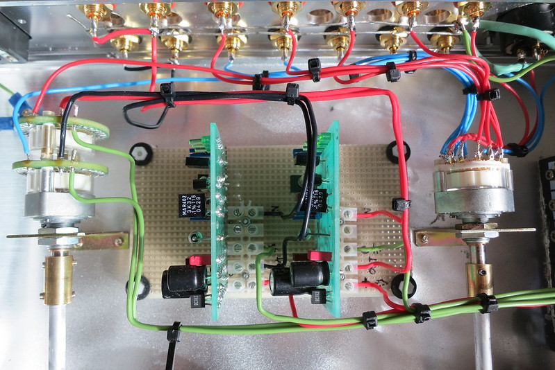
    Yes you are right red cables are signal right, blue are signal left, all signal grounds are linked together with a lead from them going back to the star ground point in the ceter of the Cap6 filter.
    In a pre amp you would normally have the one point in your system where you also make a connection between signal ground and chassis earth but this should be the only point in your overall system where you have this link or you will create an earth loop and get a mains hum.
    Some people also fit a switch in this ground to earth connection so you can lift this connection in the case of a Hum from say a problematic source complonent, you could even fit a 3 way switch so its either
    1 connected
    2 lifted
    3 connected via a resistor or diode/cap/resistor network.

    Note that the left hand switch is a Goldpoint 24 point stepped attenuator Vol control

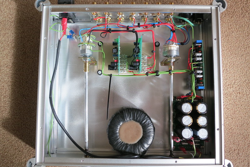
    again another shot for clarification


    IMG_2375 by Alan Towell, on Flickr

    Alan
    Turntable - Garrard 401/Jelco 750L/Ortofon Kontrapunkt B, Pioneer PLC 590, Micro Sieki MA505 , Denon DL103R - DIY Paradise Phono stage - Reel 2 Reel Studer A810, Otari MX55,Tascam BR20, Revox A77, B77, PR99, TEAC X1000 & 3440, Digital HTPC / Young Dac - Preamp - DIY B4, 821, Power Amp's DIY Avondale NCC300 Mono Block, Speakers Wilmslow Kit Volt BM220.8 / Scanspeak D2905/9500

  9. #9
    Join Date: Dec 2014

    Location: Wootton, North Lincolnshire

    Posts: 68
    I'm Chris.

    Default

    Alan,

    Thanks again for a very helpful reply.
    The earth-ground example you gave is very useful, can get on with it now.
    I like the sound ( pun?) of that attenuator..... I did consider introducing one, but the Pi DAC goes direct to the pwr amp otherwise would put the selector switch and the vol pot on the input side of the pre-amp, but only TT will be using the pre so not much point. Both go through the Muse pwr amp so both can be controlled with its volume control.
    I like the look of the rotary switch shaft extenders and connectors, may be needing something like that.
    Thanks again,

    Chris

+ Reply to Thread

Posting Permissions

  • You may not post new threads
  • You may not post replies
  • You may not post attachments
  • You may not edit your posts
  •