+ Reply to Thread
Results 1 to 7 of 7

Thread: Phonostage with balanced input

  1. #1
    Join Date: Sep 2015

    Location: Minsk, Belarus

    Posts: 30
    I'm Valera.

    Default Phonostage with balanced input

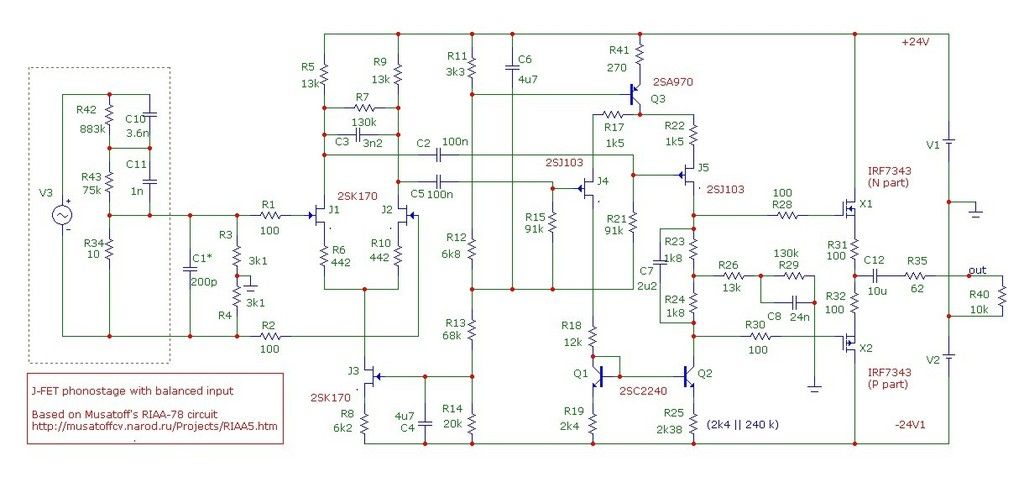
    My phonostage with balanced input based on schematic of Konstantin Musatoff described here: http://musatoffcv.narod.ru/Projects/RIAA5.htm , see also attached picture for convinience. The main features are:
    - no common feedback loop
    - passive correction
    - relative high (+/-24 V) power supply.
    - relative powerful output stage, so it should be non-sensitive to the interconnect

    Unfortunately, there is no EN translation for device, so I will describe it in short.

    R* - additional HF-correction for some cartridge with lack of HF
    R7 - tau1 (75 us)
    R26 - tau2 (318 us)
    R29 - tau3 (3180 us)
    R15, R21 - 7950 us
    R12 - bias for output stage (Q9)
    SW1 - switches between balanced and asymmetrical input

    DA1 (low-noise opamp with MOSFET input, for example LF353) and components around it works as integrator and maintain DC zero output. As you see, all correction RC-circuits are passive, i.e. there is no frequency correction in feedback. Of course, output stage Q9 works in Class A.

    So, it's basic schematic. I make some changes:

    1. C3R7 excluded, I make tau1 correction (75 us) on input by reducing R3 and R4 to 3.1 kOhm each. Calculated value is (R3+R4)=6.2 kOhm for my AT-440MLa (moving magnet, approx. 480 mH inductance). I used this solution for tau1 with different schematic a long time ago since 80-th and it works well.

    2. Integrator DA1 with it components removed, RIFA polypropylene 10 uF capacitor installed before R35. My opinion - one good PP capacitor is better than integrator circuit with a lot of active and passive details plus additional power supply for it.

    3. 2SK184 replaced with 2SK170 (or 2SK117). Reason is enough simple - I didn't find here supplier for genuine 2SK184 . Of course, all transistors in differential stages and in current mirror should be matched in pairs.

    All capacitors in "sound" way are polystyrene ones, C7 polypropylene, other big caps C4, C6 are PTFE.

    Phonostage powered by Two-transistor Shunt Regulator, it has low noise at the wide frequency range and good performance regarding 50*n Hz. Regulator recalculated to 24 V, I used two identical ones with two separated Shottky rectifiers.

    Sound. Unfortunately I'm rather technician than poet. It sounds light and airy, with soft deep bass. By the way, I don't see significand difference in sound with balanced and unbalances modes, maybe result will different with other interconnect from TT to PhS.

    Used with upgraded Technics SL-1200Mk2, MM AT-440MLa. Tonearm rewired by litz, stock interconnect replaced with DIY Klotz MC5000 (twisted pair in common shield each lead, it's very suitable for this FS) and XLR connectors, external PSU, internal onboard regulator replaced with LM317, control board fully recapped, main bearing upgraded in first iteration... I see a long way ahead!)
    RIAAPhono5.jpg

  2. #2
    Join Date: Jul 2011

    Location: London

    Posts: 741
    I'm Colin.

    Default

    Interesting circuit, I do like the idea of the shunt reg.
    But I hate the idea of DC servo on the output, I always found then troublesome.

  3. #3
    Join Date: Aug 2013

    Location: London

    Posts: 1,499
    I'm Sam.

    Default

    Owchen prekrastnui!

    (I studied Russian at school and visited Borisov - home of the 1812 victory and therefore symphony - in Belarus as part of my exchange. Sadly things like "very nice" are all I can remember now. "Slon igrayet na barabanye" = "The elephant plays the drums".)

  4. #4
    Join Date: Sep 2015

    Location: Minsk, Belarus

    Posts: 30
    I'm Valera.

    Default

    Quote Originally Posted by Colin Wonfor View Post
    Interesting circuit, I do like the idea of the shunt reg.
    But I hate the idea of DC servo on the output, I always found then troublesome.
    Yes, I also prefer more simple and straight solution. That's why my version looks as shown here (C3 removed, but I saved it's place on PCB for using in future with MC where my 75 us correction is unusable):


    Quote Originally Posted by Audio Advent View Post
    Owchen prekrastnui!

    (I studied Russian at school and visited Borisov - home of the 1812 victory and therefore symphony - in Belarus as part of my exchange. Sadly things like "very nice" are all I can remember now. "Slon igrayet na barabanye" = "The elephant plays the drums".)
    Thanks for russian words! Borisov is old city not so far from Minsk, historical Berezina crossing well known. I have vinyl Tchaikovski "1812 Overture" (canonical variation, i.e. with "God save the Tsar" ("Боже, царя храни") old russian hymn).

  5. #5
    Join Date: Aug 2013

    Location: London

    Posts: 1,499
    I'm Sam.

    Default

    Боже мой!

  6. #6
    Join Date: Jan 2009

    Location: Essex

    Posts: 32,051
    I'm openingabottleofwine.

    Default

    Valery,

    I would be interested in a balanced output version of your circuit. Could that be achieved by taking the output from the junction between the 100R resistors and the output FETs? That is, there would be two 10u + 62R combinations.

    Thanks

    Barry
    Barry

  7. #7
    Join Date: Sep 2015

    Location: Minsk, Belarus

    Posts: 30
    I'm Valera.

    Default

    I'm afraid it's not so simple and in order to get balanced output you have to take differential signals from J4, J5 FET's and make two additional output stages instead of push-pull on this schematic. Or (may be better?) to add medium-power differential amplifier instead given output. My PA has unbalanced input, so I newer think about it.

    BTW, this schematic is not mine, I took it from Konstantin Musatoff site.
    Analog: Technics SL-1200MkII (RB300 tonearm, external PSU, separated power supply for all stages, improved bearing), MC Goldring Eroica LX, custom SUT 1:10, Balanced input J-FET DIY phonostage
    Digital: Cubietruck (headless Debian server, i2s output, external masterclock from DAC), content on HDD. DAC: Lynx D29v4 (Altera FPGA digital stream separator, 2*AD1853, 2*3 OP42 LPF)
    PA: DIY composite amplifier YES-3, schematic by Gennady Bragin
    Acoustic: DIY floorstanding 3-way SB Acoustics

+ Reply to Thread

Posting Permissions

  • You may not post new threads
  • You may not post replies
  • You may not post attachments
  • You may not edit your posts
  •