+ Reply to Thread
Page 2 of 3 FirstFirst 123 LastLast
Results 11 to 20 of 25

Thread: Adding remote control to an LDR pre.

  1. #11
    Join Date: Sep 2013

    Location: North Island New Zealand

    Posts: 1,757
    I'm Chris.

    Default

    Hi Richard
    Is the 100k you are using a log or a linear type ? Your findings suggest leaving the gain
    of the circuit as is. Boards since August have replaced former diodes with transistors
    and more recently have rearranged components to greatly assist. I will try and get
    yourself and Rupert one of these before New Year. Yes J2 control board ground now needs connection
    to your star ground earth.

    Cheers / Chris

  2. #12
    Join Date: Dec 2015

    Location: Leeds

    Posts: 46
    I'm ian.

    Default

    Excellent job, I was thinking of doing something similar with my LDR.
    Was it worth the trouble would you say?

  3. #13
    Join Date: Apr 2012

    Location: United Kingdom

    Posts: 2,302
    I'm Richard.

    Default

    Quote Originally Posted by daddydj View Post
    Excellent job, I was thinking of doing something similar with my LDR.
    Was it worth the trouble would you say?
    NO!
    After having to make a new case, bodging a fix to make a 5.1 remote into a true 5 way, discovering that adding resistors to a 100k pot to get a decent amount of travel changed the sound (for the worse; I have no idea why that is so!), getting up to change the volume or inputs doesn't seem so bad. I may even go back to manual!
    A simple unit has now become over complicated for no real benefit, but I am retired and got bored, so the challenge was interesting. Don't bother, is my advice.
    ABD.

  4. #14
    Join Date: Apr 2012

    Location: United Kingdom

    Posts: 2,302
    I'm Richard.

    Default

    Quote Originally Posted by Light Dependant Resistor View Post
    Hi Richard
    Is the 100k you are using a log or a linear type ? Your findings suggest leaving the gain
    of the circuit as is. Boards since August have replaced former diodes with transistors
    and more recently have rearranged components to greatly assist. I will try and get
    yourself and Rupert one of these before New Year. Yes J2 control board ground now needs connection
    to your star ground earth.

    Cheers / Chris
    Thanks Chris.
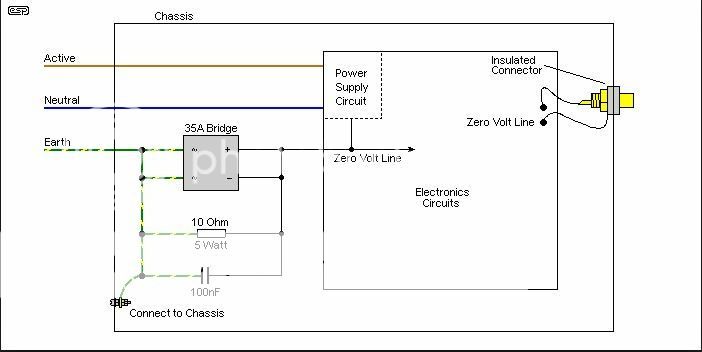
    The pot is 100k log. I always did run a ground wire to the star ground, which is lifted from chassis ground with a 20 ohm resistor, like this.

    I will have to experiment with lifting or combining some of the ground wires, as it has more hum than my TVC. But at the moment I am concentrating on building a simple valve tester, as I have a load of old valves. http://www.valveheaven.com/wp-conten...lve-tester.pdf
    ABD.

  5. #15
    Join Date: Sep 2013

    Location: North Island New Zealand

    Posts: 1,757
    I'm Chris.

    Default

    Quote Originally Posted by awkwardbydesign View Post
    Thanks Chris.
    The pot is 100k log. I always did run a ground wire to the star ground, which is lifted from chassis ground with a 20 ohm resistor, like this.

    I will have to experiment with lifting or combining some of the ground wires, as it has more hum than my TVC. But at the moment I am concentrating on building a simple valve tester, as I have a load of old valves. http://www.valveheaven.com/wp-conten...lve-tester.pdf

    Hi Richard
    My thoughts are to use the cathode returns J40 and J25 instead of the normal anode way of adjusting volume.
    I will try it relative to 100k resistance and report back. Diagram attached shows how it may work.
    cathode volume control.pdf

    As the wiper being ground gets closer to say series cathode j40 it is in effect turning the internal led ON and causing the series pair to lower
    their signal side resistances, and the shunt pair progressively off via 100k resistance, if volume was fully on. I think your 100k may be ideal then
    as the voltage at the cathode is always lower than at the anode. So in effect you would rearrange j40 and J25 wiring to be
    the upper and lower arms of the pot, and the wiper to be ground. Anodes would be fed straight from J1 control board out
    via your balance control. Let me test it !

    Cheers / Chris

  6. #16
    Join Date: Apr 2012

    Location: United Kingdom

    Posts: 2,302
    I'm Richard.

    Default

    Thanks Chris. Bear in mind I have split the 2 halves of J27 and put a 470R balance pot across them. That would need to be re-organised.
    (I think it's J27; without opening it it's hard to remember!)
    ABD.

  7. #17
    Join Date: Sep 2013

    Location: North Island New Zealand

    Posts: 1,757
    I'm Chris.

    Default

    Hi Richard
    The method of using J40 and j25 as connections to the pot and the
    pot central leg grounding, works. I have tried it just observing resistance
    so far, and it copies as a 100k pot to give, 36k travel for the shunts
    and just over 40k travel for the series. This was with NSL32SR3

    I need to listen to it connected this way, but from what I am measuring it is very
    controlled in volume adjustment. ...and of course nothing better to do on Xmas day

    Will give it a listen, and report back.

    Cheers / Chris

  8. #18
    Join Date: Apr 2012

    Location: United Kingdom

    Posts: 2,302
    I'm Richard.

    Default

    Thanks, Chris, and Merry Christmas. Or is it Boxing day there already?
    ABD.

  9. #19
    Join Date: Apr 2012

    Location: United Kingdom

    Posts: 2,302
    I'm Richard.

    Default

    Hi Chris. Hope you had a good Christmas.
    A question about wiring the cathode volume control. How do I connect the earth wiring? There are 2 connections each to J40 and J25, so is one of them still earth, and I only connect the pot to the other one? This is my layout at the moment, 2 boards piggybacked with the shunt LDRs on the top board. J27 is split for the balance pot. The star earth post is insulated from the case, with a switch to vary the connections.
    I'm a bit confused as to how the earthing will be organised now. And have I got too many earth connections?
    ABD.

  10. #20
    Join Date: Sep 2013

    Location: North Island New Zealand

    Posts: 1,757
    I'm Chris.

    Default

    Hi Richard
    Very quiet Xmas , but very nice too lots of nice walks, hope yours went well.

    Thanks for your PM to steer me to your post. With cathode volume control, we are just chassis grounding
    the signal ground, and you have correctly wired that at j25 lower. the other ground connections are
    control board J2 also star grounded, but we have a new ground to make which is now the wiper of the pot.

    You can do all of this without lifting the upper LDR board to reveal the lower board, by knowing exactly
    the wire from j40 upper and J25 upper which are the cathodes. hopefully your wire length will be
    suitable to extend J40 upper (previously ground ) from each board now to the RHS of Pot , and
    j25 upper from each LDR board to the LHS of pot.

    So disconnect j40 upper each board -2 wires and J25 upper - 2 wires
    from your very neatly wired star earth, these need to go to J40 RHS leg of the pot
    and J25 LHS of the pot.

    Where previously you wired Right Hand Side leg of pot to pole of switch then via contacts to series anodes
    and Left Hand Side of Pot to the Shunt anodes you would now have J1 control board OUT with a wire directly to
    shunt anodes - yours running via a 2.5k pot to balance current left to Right across the shunt LDR's
    so its wiper wire this to J1 ..... next the same for the series LDR now by the looks of it running to common of the relays
    NO ( normally open ) connecting to each anode- when coil is activated. .... wire this also to J1

    you should be able to steal these off the RHS and LHS of the pot... all now wired to J1
    and central leg of pot wire --- this is now grounded.

    With cathode volume the steering of current to shunt and series LDR;s is being done via the separation
    on the LDR board of shunt cathode completely separate to series cathode. So just at the other end of the circuit.
    How this works is that there is a potential difference between ground ( now wiper of the pot ) and the current
    seeking ground ( really a potential difference ) from the cathodes. Voltage at the cathodes is going to be
    J1 less the LDR forward voltage. so likely about 6.7 volts at the cathodes as J1 on model of control board will be
    7.5-8v

    So with some forward planning you should not have to make too many alterations to wiring ut there will be some,
    rather you should be able to rearrange same wires to do different wiring for cathode volume.

    I am online for another few hours and will help you tomorrow when I wake up.

    Cheers / Chris

+ Reply to Thread
Page 2 of 3 FirstFirst 123 LastLast

Posting Permissions

  • You may not post new threads
  • You may not post replies
  • You may not post attachments
  • You may not edit your posts
  •