+ Reply to Thread
Page 2 of 2 FirstFirst 12
Results 11 to 19 of 19

Thread: G-Ohm circuit diagrams.

  1. #11
    Join Date: Jul 2014

    Location: Hertfordshire

    Posts: 431
    I'm Graeme.

    Default

    Quote Originally Posted by Syncopator View Post
    Thank you for pointing that out Firebottle.

    What a stupid mistake. After lifetime in electronics too. Rather embarrassing actually. I will correct it a little later today - when I've properly woken up.

    Addendum: There, done. I'm still engaged in a bout of self recrimination. My mind was in neutral. Just gawping at the graphics and not reading the circuit.

    It serves the purpose, though, of reminding me of my 'phone conversation with Michael. Asked what value of idle current he set for the output f.e.ts, he said it was done while reading the distortion, not a target current.
    David,

    Thanks very much for the drawings. I'm slightly surprised that you left the fuse in the drawing that you did for the Power amp, when Michael's drawing shows it is replaced with a relay - certainly my units have relays fitted. I also have a couple of doubts on the resistor values but I'll have to check my notes later.

    P.S. I'm struggling to identify the zener diodes used in the PSU to control the voltage out to the pre-amp. On one of my units these are fitted to the back of the pre amp power output socket. On the other unit this whole part of the circuit is missing. Would you have any information on the zeners?

    Many thanks,

    Graeme

  2. #12
    Join Date: Jul 2014

    Location: Hertfordshire

    Posts: 431
    I'm Graeme.

    Default

    Quote Originally Posted by Firebottle View Post
    With the amp I serviced I originally set the full circuit current to 100mA per channel, so probably about 90mA through the FETs.
    The heatsink became warm with no music throughput so I backed it off to circuit current of 75mA and left it at that. Could probably get away with a lot less.

    Hi Alan, Can I ask at what points you checked the circuit current? I know how to do this job on Quads, and A&R A60's, but I've not done so on the Myst's.

    Thanks,

    Graeme

  3. #13
    Join Date: Oct 2012

    Location: The Black Country

    Posts: 6,089
    I'm Alan.

    Default

    With the example that Jerry had the wiring need tidying up in the psu, so I just interrupted the feed to each channel and connected an ammeter.

    That's why I'm referring to 'circuit current', that is including the protection relay current and the driver circuit. The values I quoted earlier where not the actual ones now I think about it, the protection relay takes about 40mA and I left the final overall setting at about 100mA, so about 50mA through the FETs.

    I love Hendrix for so many reasons. He was so much more than just a blues guitarist - he played damn well any kind of guitar he wanted. In fact I'm not sure if he even played the guitar - he played music. - Stevie Ray Vaughan

  4. #14
    Join Date: Sep 2015

    Location: Lincolnshire

    Posts: 17
    I'm David.

    Default

    Quote Originally Posted by Desmo View Post
    David,

    Thanks very much for the drawings. I'm slightly surprised that you left the fuse in the drawing that you did for the Power amp, when Michael's drawing shows it is replaced with a relay - certainly my units have relays fitted. I also have a couple of doubts on the resistor values but I'll have to check my notes later.

    P.S. I'm struggling to identify the zener diodes used in the PSU to control the voltage out to the pre-amp. On one of my units these are fitted to the back of the pre amp power output socket. On the other unit this whole part of the circuit is missing. Would you have any information on the zeners?

    Many thanks,

    Graeme
    The drawing sent to me Michael was a copy from the TMA3 booklet - those are his corrections on the sheet. Can't comment about the resistor values other than to say that Michael, having modified some of the capacitor figures, would probably have done the former too. Since it is easy to do, I will replace the fuse in the diagram with a pair of relay contacts.
    Next time I open the unit I will check.

    I don't understand " ... fitted to the back of the pre amp power output socket. On the other unit this whole part of the circuit is missing." Will you elaborate.

    Regarding the power supply, I don't remember what's in there. When I have the enthusiasm I'll take a look in there too.

    Regards,

    David
    Last edited by Syncopator; 07-09-2015 at 08:42. Reason: correction
    Equal rights for equal responsibilities.
    Equal opportunities for equal abilities.

  5. #15
    Join Date: Aug 2008

    Location: notts uk

    Posts: 296
    I'm Pete.

    Default

    Just spotted this thread ...curcuit looks like adaption of the maplins mosfet module .......with newer components ? I made a number of the maplin modules and damn fine sounding they were too. They ran quite hot ...and need about twice the cooling/heat sink area than recomended in the instruction otherwise they had a habit of frying themselves .

  6. #16
    Join Date: Sep 2015

    Location: Lincolnshire

    Posts: 17
    I'm David.

    Default

    Quote Originally Posted by zanash View Post
    Just spotted this thread ...curcuit looks like adaption of the maplins mosfet module .......
    Good morning zanash, it's one of the many spin-offs from a Hitachi circuit, the details of which are in the link which was in post #4 (http://www.angelfire.com/sd/paulkemble/sound7g.html)
    Equal rights for equal responsibilities.
    Equal opportunities for equal abilities.

  7. #17
    Join Date: Oct 2012

    Location: The Black Country

    Posts: 6,089
    I'm Alan.

    Default

    Hi Pete,

    The Myst amplifiers came before the Maplin mosfet modules, all spin offs from the Hitachi circuit as David says.

    The beauty of advancing mosFET technology is that with the same circuit but up to date FETs the waste heat dissipation is now a lot less
    I love Hendrix for so many reasons. He was so much more than just a blues guitarist - he played damn well any kind of guitar he wanted. In fact I'm not sure if he even played the guitar - he played music. - Stevie Ray Vaughan

  8. #18
    Join Date: Sep 2015

    Location: Lincolnshire

    Posts: 17
    I'm David.

    Default

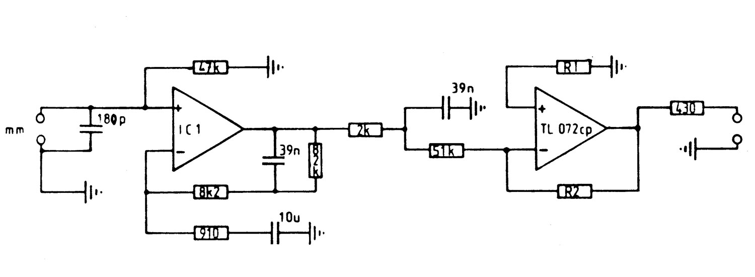
    I asked Myst if they still had the G-Ohm paperwork. Michael kindly replied, saying that the only thing he could find is the disc input circuit for the TMA3, which will be inserted below.

    So .... I shall have to spend a bit of time inspecting the innards and wielding a pencil again.

    Equal rights for equal responsibilities.
    Equal opportunities for equal abilities.

  9. #19
    Join Date: Oct 2012

    Location: NE England

    Posts: 4,173
    I'm Jez.

    Default

    For nearly all lateral mosfet amplifiers that are not class A 100mA is a universal "correct" quiescent current. It's not critical and it does result in rather more heat generation than the average bipolar transistor amp of the same rating.

+ Reply to Thread
Page 2 of 2 FirstFirst 12

Posting Permissions

  • You may not post new threads
  • You may not post replies
  • You may not post attachments
  • You may not edit your posts
  •