All right. One down, one to go.
I've been mentioning making another PSU for awhile now, and I finally made some actual progress. Nothing is complete yet, nothing cast in stone, but here is the basic idea -
This is as good a place as any to explain a few things, although I know many of you will just skip this and look at the other photos...
The transformer is something I found in the surplus store, it's awfully close to what I would want if ordering something custom, and saves me a long search for a catalog item of similar spec. It's a custom toroid for Grace Audio designs. The windings have more than enough current for the job.
Motor Supply Looking at the top circuit, you see the motor drive.
The secondaries will be in series, giving about 50V after the bridge. This will be sent to a big CRC, then to a Pass 'Zen Regulator' from Zen Variations 3 -- www.firstwatt.com/pdf/art_zv3.pdf I'm using the zen reg for a few very important reasons - 1) there is some excess voltage to drop before the LM317 input, 2) this reg will free the LM317 from dealing with most of the line variations, 3) I have wanted to try this for a while and have all the parts on hand. But honestly, It's mainly about dropping the excess voltage.
After the ZenReg, a bog-standard LM317 circuit will be used with one twist - it will be elevated by 6.9V as it will sit on top of an LM329 precision voltage reference. Why? To give the 317 an easier job of regulation (as the top of the 329 will be rock solid in respects to ground), to help isolate the 317 from any grunge upon ground, as well as keeping the input-output voltage of the 317 lower than it's maximum. (And I have some and want to play with them...)
More detail can be found in this diagram -
And an image of the ZenReg, for those interested (Image courtesy of Nelson Pass)
Cool.
Logic supply -
The 10VAC winding of the transformer will be sent to a PCB with bridge, large cap, and LM317. The caps will not be enormous, as it's important for the logic supply to get to voltage faster than the motor supply.
Strobe supply
This one is a bit fun, the strobe voltage will be made by connecting a small 12V transformer 'backwards' to the 10VAC winding of the main transformer. That voltage will then be rectified and sent to a Supratex LR8 regulator, which can take a maximum input voltage of 450V ! Neat.
A few more photos -
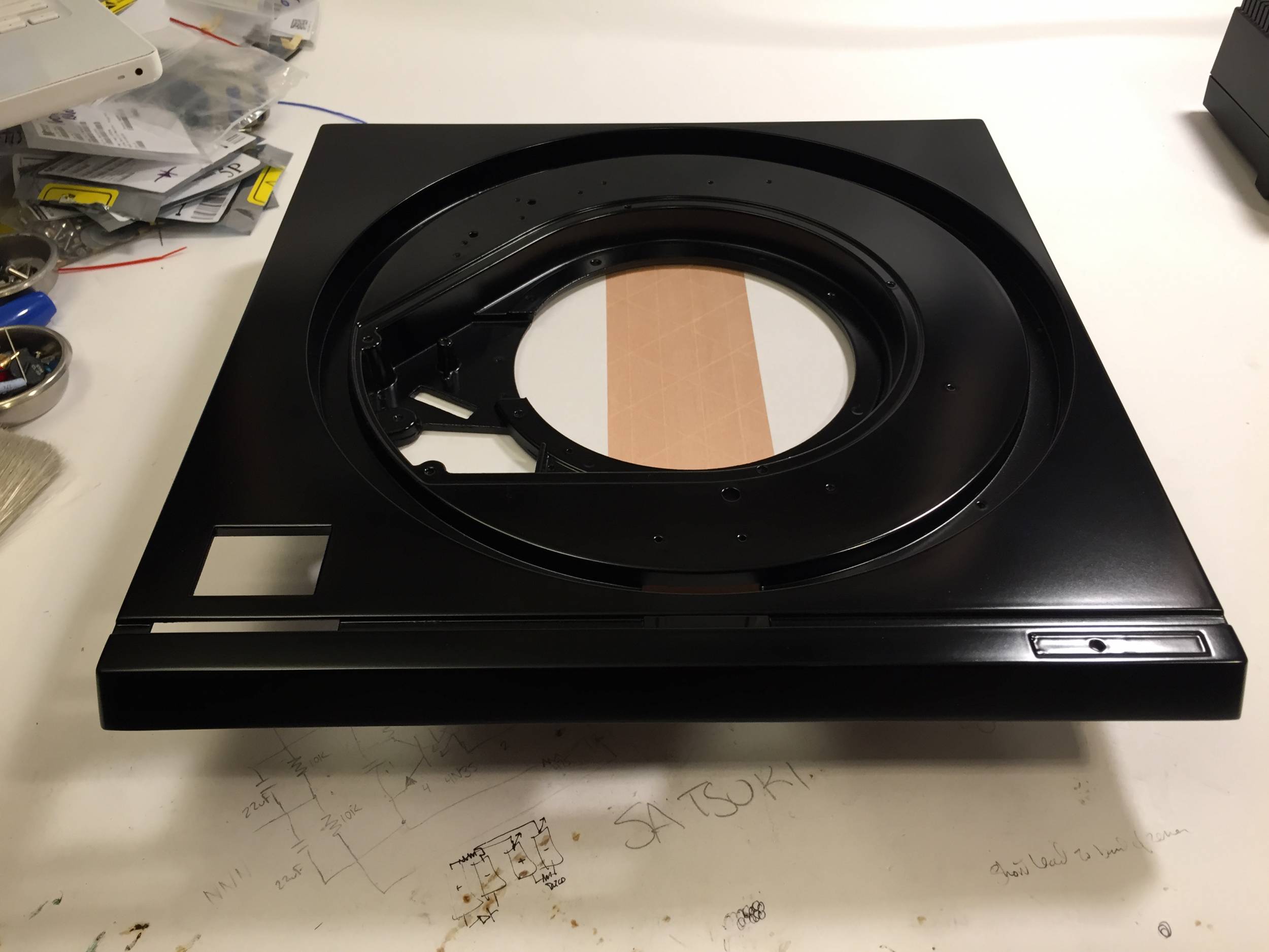
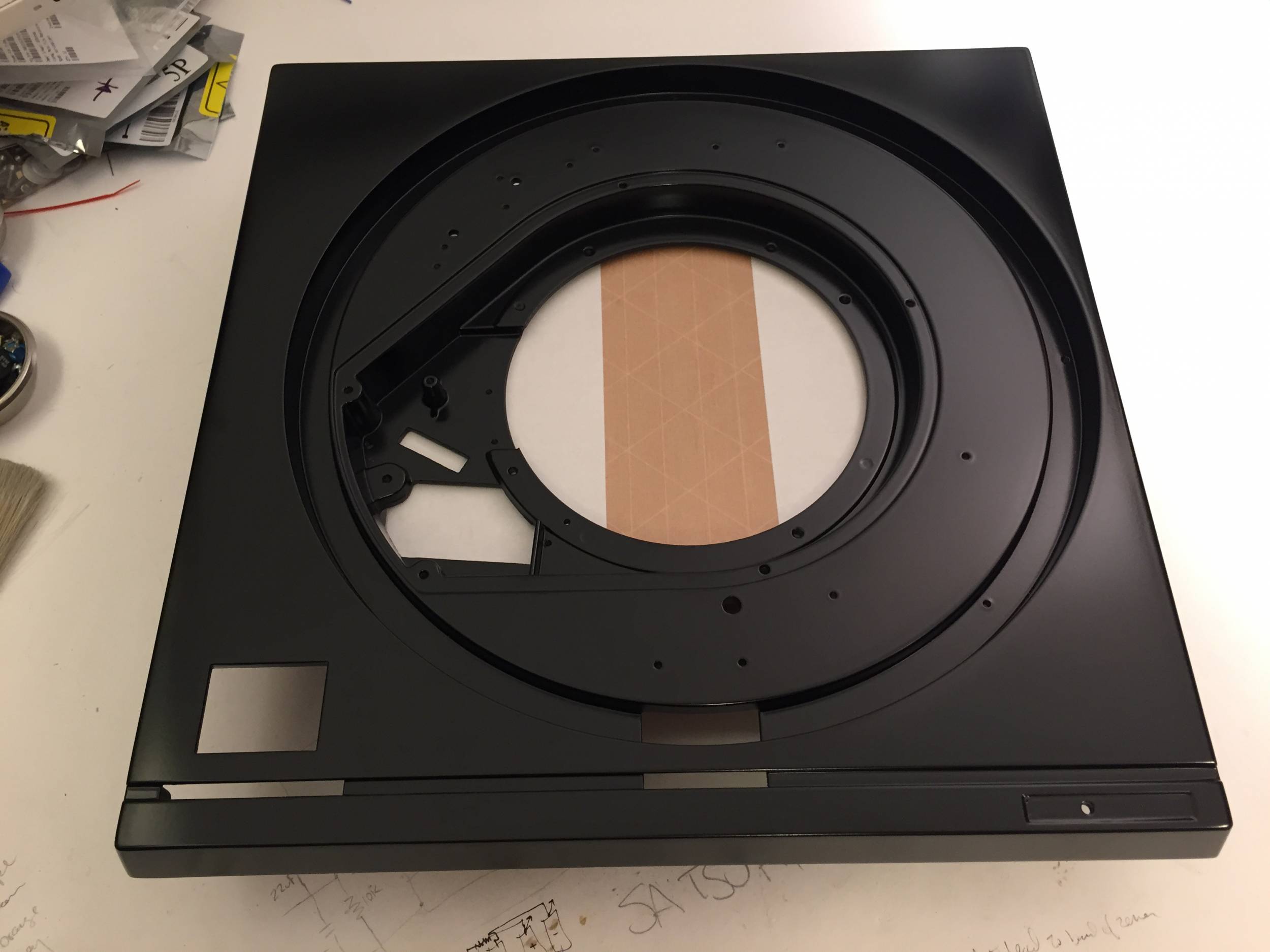
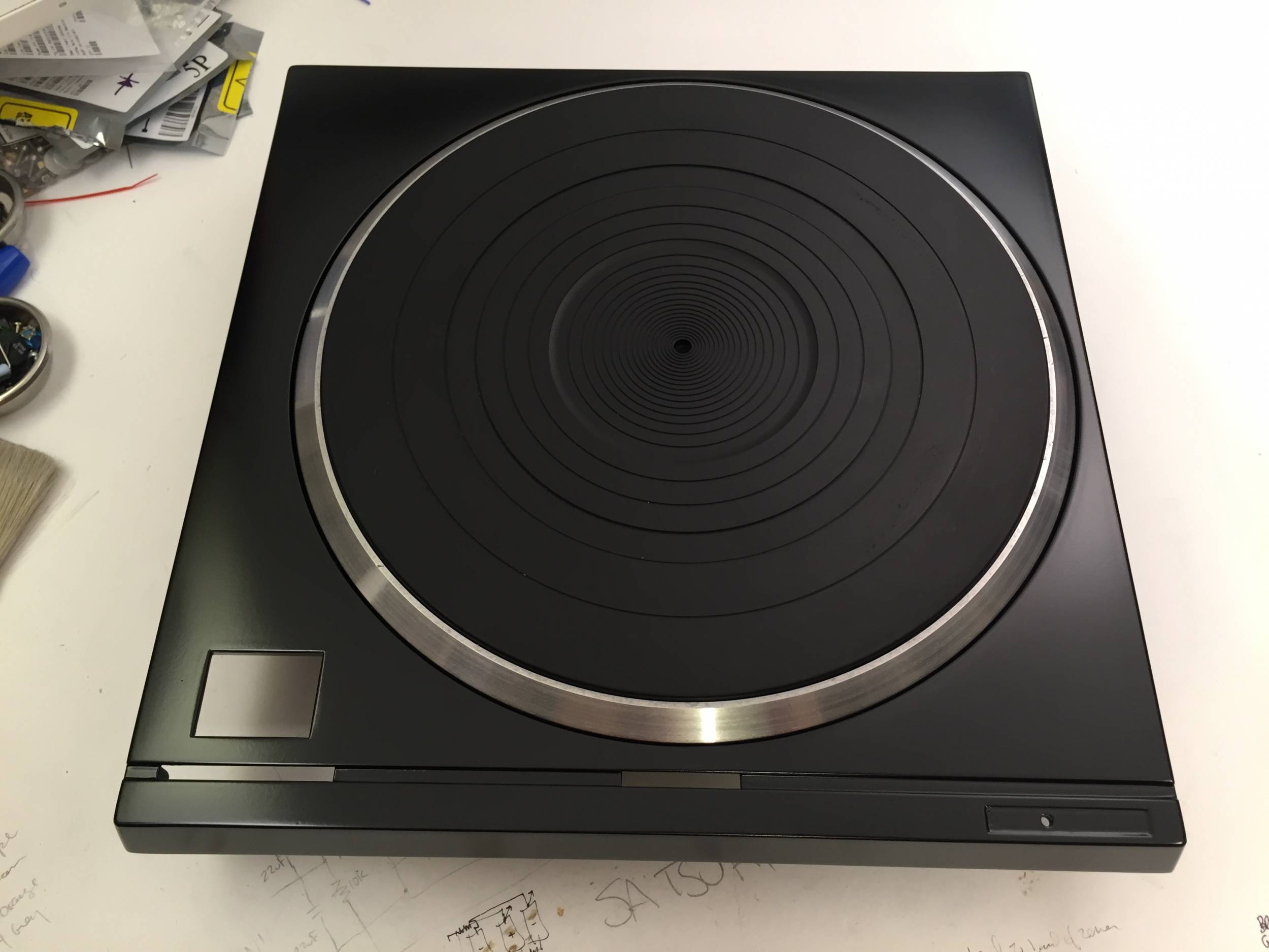
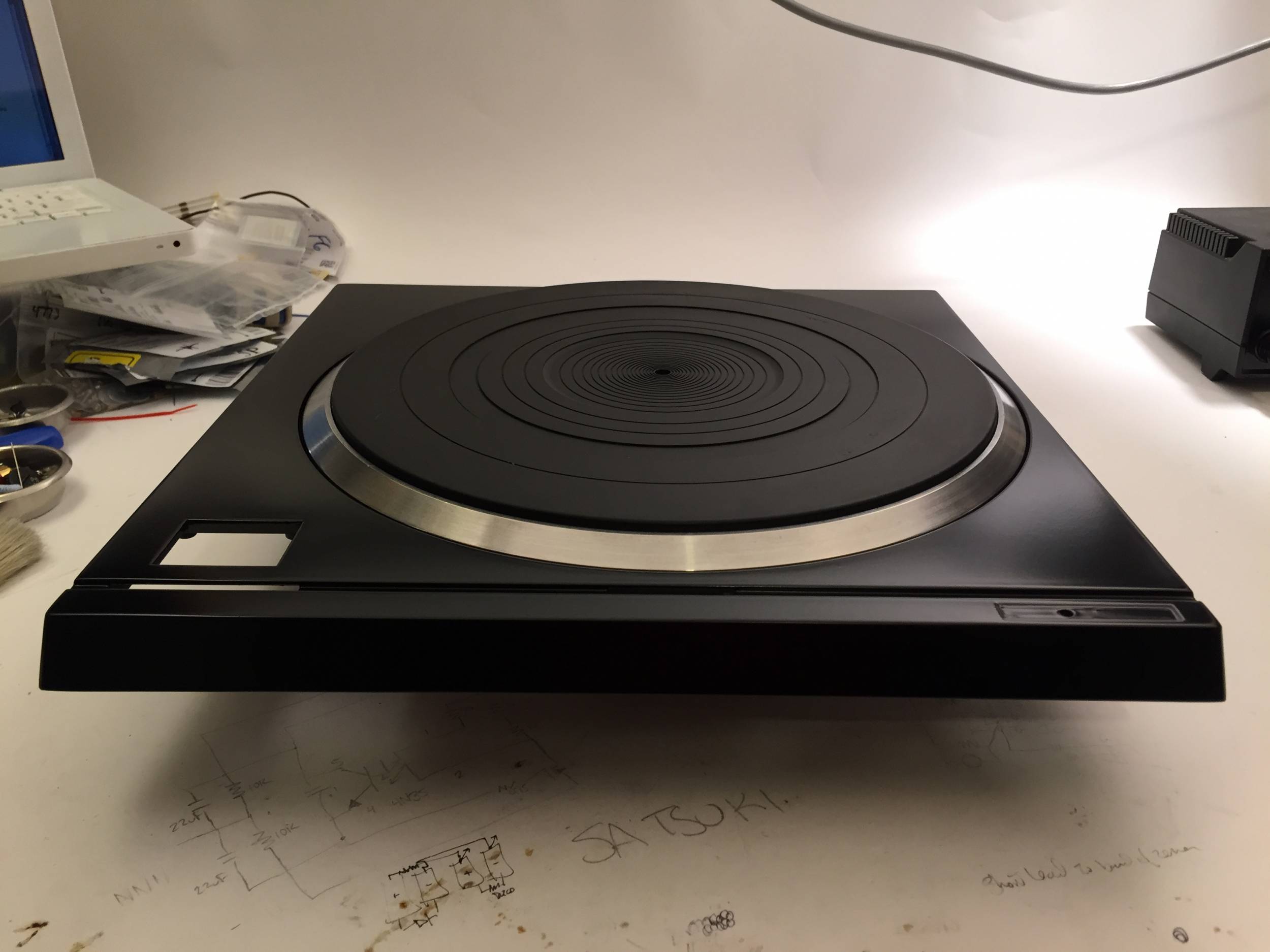
The chassis it will all be placed into.
Testing the ZenReg.
The ZenReg. The plan is to use the chassis itself as the heatsink, and the circuit is built on perfboard. Heatshrink has been used to insulate the assembly from the chassis wall as well as cover up the messy wiring job.
Comments, criticisms, and questions are warmly solicited.


 Reply With Quote