+ Reply to Thread
Page 22 of 34 FirstFirst ... 12202122232432 ... LastLast
Results 211 to 220 of 340

Thread: Renovation of Celestion 66 Studio Monitors

  1. #211
    Join Date: Jan 2013

    Location: Carlisle - UK

    Posts: 1,973
    I'm Ken.

    Default

    Hi Paul

    Re-spacing and positioning the coils is not guaranteed to work, but its about the only thing I've not tried.
    My gut feeling is the resonance is inherant with the type of band pass filter used, but it is worth trying as you suggested, as new boards are being made anyway.

    I'm in the process of doing just that. I was going to buy new coils but having spent a lot on experimenting allready I decided to re-use the stock items. I will have to carefully remove them from the board they are allready stuck to. Another reason for keeping them is that all my other part values have been derived using these, which do not measure to the exact values that Celestion quote on their drg. Getting new coils with the same Inductance and RCD values would be tricky, although not impossible to find within a very close margin (Jantzen air core) but would add another £60 to the build.

    I'm finalising cap values/make and L-Pad values for driver attenuation at the moment and then doing an alternate layout on a much larger board (310 x 260mm). This is the largest that will fit through the ABR driver aperture. I have the Paxolin board and the brass eyelets arived this morning for making the solder points on the boards, so not far off.

    The new board will sit behind the ABR unit away from the big Bass driver magnet and will have six 15mm diameter holes in it just below the centre so I can get to the six binding posts mounted behind it, so as to make the conections. I didn't want to move the binding posts for originality reasons. The two second largest coils (2.2mH) will be moved further away from the largest coil and turned on their side with the axis at 90 degrees to the large one. The other two small coils will be positioned away from these and avoiding their axis lines. That should do the trick.

    I'll post some pictures when I get these boards done.

    Need to get a wiggle on as I want them compleated and run in for NEBO5 on 10th January.

  2. #212
    Join Date: Jan 2012

    Location: leicestershire

    Posts: 694
    I'm John.

    Default

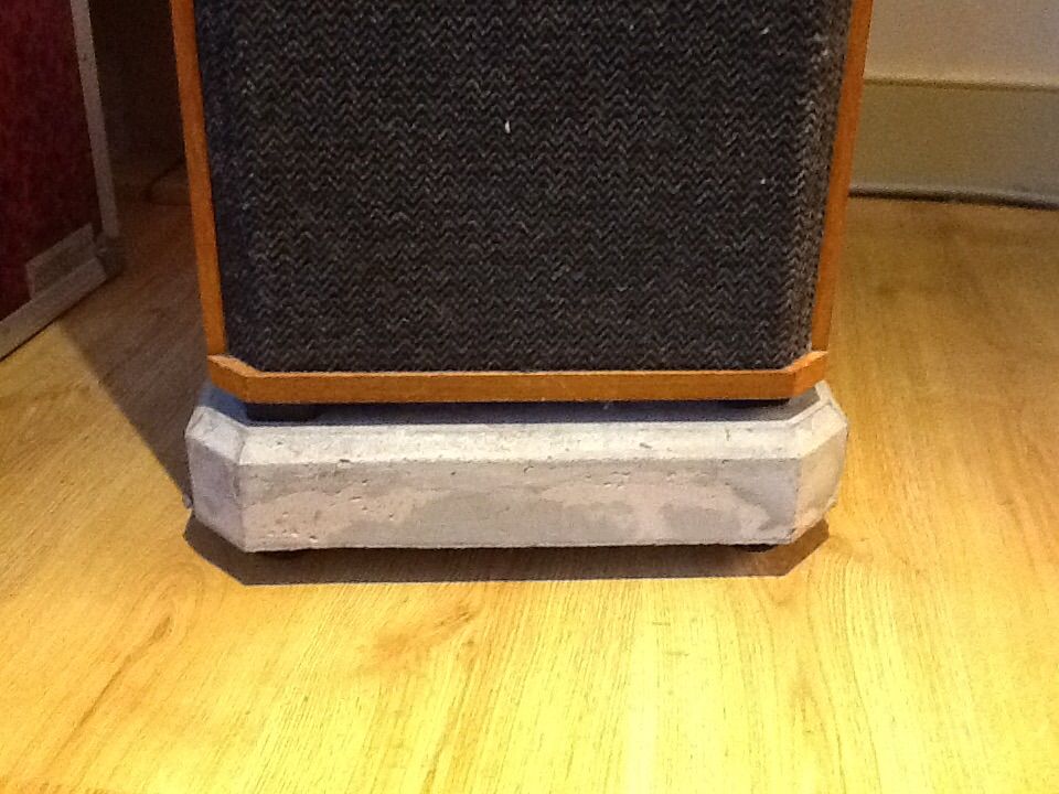
    Thanks for the loan of the 66 base moulds Ken......ok mine still have a "little bit" of cosmetic work to do to match yours, but I'm happy with the results so far.

    Anyone else want a loan of the moulds?

    Cheers
    John


    Quote Originally Posted by Qwin View Post


    That's the first of the plinths completed, spirit bubble set into the top and carpet spikes installed and adjusted through the four holes in the top face. Each plinth weighs over 20Kg.


    I'm pleased with the appearance, I think the base compliments the speaker.
    The spikes have been adjusted so the base is only just clear of the carpet, which makes it look well anchored visually and not floating. The thickness of the base and the gap created by the "Soundcare" feet, have good proportions and work well together. It only remains for me to complete the second plinth which is out of the mould and requires finishing cosmetically.
    ----------------------------------------------------------------------------------
    Technics 1210/Mike New Bearing/Jelco SA750d/Goldring 2500/Paul Hynes SR5 21/27.
    Cambridge Audio 840c CD. Squeezebox Touch. Synology NAS.
    Teac A-3440.
    Beresford Bushmaster.
    Quad II monoblocks....Quad 44/405.....Croft Micro.....Cambridge Audio 840.
    Celestion Ditton 66.....KEF Reference One

  3. #213
    Join Date: Mar 2012

    Location: Gloucestershire

    Posts: 3,377
    I'm Paul.

    Default

    Quote Originally Posted by Qwin View Post
    Hi Paul

    Re-spacing and positioning the coils is not guaranteed to work, but its about the only thing I've not tried.
    My gut feeling is the resonance is inherant with the type of band pass filter used, but it is worth trying as you suggested, as new boards are being made anyway.

    I'm in the process of doing just that. I was going to buy new coils but having spent a lot on experimenting allready I decided to re-use the stock items. I will have to carefully remove them from the board they are allready stuck to. Another reason for keeping them is that all my other part values have been derived using these, which do not measure to the exact values that Celestion quote on their drg. Getting new coils with the same Inductance and RCD values would be tricky, although not impossible to find within a very close margin (Jantzen air core) but would add another £60 to the build.

    I'm finalising cap values/make and L-Pad values for driver attenuation at the moment and then doing an alternate layout on a much larger board (310 x 260mm). This is the largest that will fit through the ABR driver aperture. I have the Paxolin board and the brass eyelets arived this morning for making the solder points on the boards, so not far off.

    The new board will sit behind the ABR unit away from the big Bass driver magnet and will have six 15mm diameter holes in it just below the centre so I can get to the six binding posts mounted behind it, so as to make the conections. I didn't want to move the binding posts for originality reasons. The two second largest coils (2.2mH) will be moved further away from the largest coil and turned on their side with the axis at 90 degrees to the large one. The other two small coils will be positioned away from these and avoiding their axis lines. That should do the trick.

    I'll post some pictures when I get these boards done.

    Need to get a wiggle on as I want them compleated and run in for NEBO5 on 10th January.
    Sorry for tardiness of late response Ken.

    I'm not at all sure about electrical resonance as the cause of what you are hearing but am curious as to what you mean by that and why you think it is in any way a culprit? My experience of vintage factory supplied Celestion crossovers to date is that (being very polite about them) they were a very mixed bag indeed. They paid little or no attention to inductor spacing or orientation, or even how tightly the inductors were wound (some I have seen are very loose and a candidate for microphonic issues); the factory capacitors or circuits doing the rounds vary because often the values were made up of what they had to hand, so all in all, it takes some investigation to get the precise figures originally designed and tested for plus there (imho) is very little merit in replicating the existing layout or quality as it has such potential (as you are discovering) for improvement.

    The best thing for most Celestion X-overs, if space and aesthetics allow, is to take them external (the same could be said for all crossovers), use optimum inductor spacing and orientation, junk the existing inductors and use only tight machine would modern equivalents. Electrolytics used much above 8 to 10KHz can safely be replaced with polys without having to be overly concerned about ESR differences. Typically from 10KHz onwards, 4 to 8 Ohm driver caps in poly will be around 0.1Ohm ESR which is similar to low loss electrolytics except that they wont suffer value drift to anything like the same degree with temperature rise.

    I can't help but think that adopting standard, as they left the factory layout is a recipe for inductive coupling (and other issues) and until the layout and components are optimised then speculation about audible distortions wont really get to the heart of the matter. It may be worth using DATs or something similar to also do a rub and buzz test on both mid drivers and tweeters to rule out a possible driver issue. Acoustic measurement of each driver rolloff point is also a good idea (haven't you got a calibrated mic now?) as this will at least show you if there's any undue overlap in acoustic crossover points which may be resulting in audible phase differences about the crossover point. Lots of work I know, but to perfect crossovers for a worthwhile project such as this, it is worth the effort for the end result.

  4. #214
    Join Date: Jan 2013

    Location: Carlisle - UK

    Posts: 1,973
    I'm Ken.

    Default

    Hi paul

    I have multiple drive units (eg 6 original tweeters not counting the Seas and 4 mid drivers) and they all measure well (very well) and sound fine.
    If I disconnect two of the three in a cabinet and just listen to the tweeter or mid driver in isolation, the resonance is not there at all on the tweeters and only very slightly on the mid drivers.
    Connect the tweeter and mids at the same time and resonance increases and comes mainly from the tweeters.

    As for the coils, mine are not wound particularly tight so some mechanical resonance might be going on there. I am in the process of making new boards with better spacing, so that might help if interaction is the cause of any distortion.

    My thoughts on the resonance being electrical came from reading about this type of band pass filter and that putting a cap and coil in series is electrically resonant the technicalities on tuning this resonance lost me but it made sense of what I am hearing. The resonance manifests as distorted raspy edginess to vocals in particular and occasionally on acoustic guitar and even certain trumpet notes. More noticeable at higher listening levels it drives me mad. Its not sibilance it sounds different.

    As for Celestion using what ever was at hand for caps, I think it was a bit more structured than that. From what I have seen they changed cap types along the way as part of their other continuous developments and quite often cap changes coincide with other mods, they would order what was available at that time, and once changed rarely went back. You can almost age a speaker by the caps used.

  5. #215
    Join Date: Jan 2013

    Location: Carlisle - UK

    Posts: 1,973
    I'm Ken.

    Default

    Looking good John,

    Just fill the minor cavities in the surface with Tetrion or any other cement based out door filler and rub it down lightly with medium grade paper on a block. It is easy to sand and the whole thing will then take a few coates of Acrylic (water based) paint applied with a small gloss roller. I just used Wilko brand satin black. Do not be tempted to give it a coat of PVA to seal prior to painting, this does not work and forms a poorely bonded skin that rubs off easily. Just apply the paint and the first coat sinks in to the porous surface and gets a good key.

    If anyone wants to use the mould, arrange to pick it up from John, otherwise he will bin it, as I have no further use for it.
    I have some instructions I printed out for John and could e-mail them to anyone wanting to have a go.
    Last edited by Qwin; 09-12-2014 at 22:41.

  6. #216
    Join Date: Jan 2013

    Location: Carlisle - UK

    Posts: 1,973
    I'm Ken.

    Default


    This is my layout for the new board.
    The High/Mid/Low filters have been separated and will connect to the three sets of binding posts already fitted. Coils have been re-spaced/oriented to avoid interaction.

    Note: This is the biggest board that will go through the ABR aperture and is 310 x 260mm or 12 3/16" x 10 1/4".

    You have to angle the board as it goes in, going from vertical (speaker laid on its back) and rotating to horizontal in its final location. This means the board has to be smaller than you might think. I have cut a piece of 3mm ply and tried it, it only just fits.

    Note: It is mounted behind the ABR to get it away from the big magnet on the Bass driver.

  7. #217
    Join Date: Mar 2012

    Location: Gloucestershire

    Posts: 3,377
    I'm Paul.

    Default

    Looks good Ken. Yes, a cap and coil in series can result in electrical resonance but it's usually damped sufficiently by the inductor impedance where designed in crossovers. I still think it's partly down to loose wound coils placed in the wrong orientation too close. Until those obvious defects are corrected, you'll not really establish whether is electrical resonance or not resulting in audible distortions, that was the point really.

    I have a different view on Celestions having seen the inside of a fair few pairs now. It wasn't just them but many other manufacturers often used what was to hand to make values up...it was not quite as structured as some would like to think back in the day! This would have affected the minority I suspect, which is why you still see most using the same values/make-up of values. One doesn't have to think too hard on this as they didn't take the trouble to wind coils tightly enough nor orientate them correctly. It would hardly be surprising then to learn that many manufacturers, Celestion included, may have used what was to hand when needed for making up values.

  8. #218
    Join Date: Oct 2013

    Location: Wrexham

    Posts: 1,058
    I'm Darren.

    Default

    Hi Ken,

    I see you've reverted to polyprops for the Mid. I tried the Alcaps but ultimately preferred the PP's, although haven't tried PP's combined with a 4uF Alcap yet. Apologies if this is a stupid question but what are the pink rectangles in your schematic?
    Darren.
    Listening Room.
    UNDER CONSTRUCTION
    Turn Table. Garrard 401, Reso Mat, 2 Tier Slate Plinth, DIY Hadcock GH242, Nick G modded Lentek, Denon DL-103.
    Pre Amp. Croft Super Micro2. Power Amps Quad 405 Mono Blocks.
    Speakers. TBC

    Home Cinema.
    UNDER CONSTRUCTION
    DAC/Pre Amp. Denon AVC X3700H.
    BDP/Streamer. Panasonic DP-UB820EB / Apple TV4K.
    Display. Optoma UHD51 / DIY False Black Window Screen.
    Power Amps. 2 x Nakamichi AVP1.
    Front Speakers. DIY Baby Celestion Ditton 66. Surround Speakers. Celestion Ditton 11. Subwoofer. BK Electronics P12 300SB PR.

    Old Gallery. http://theartofsound.net/forum/showt...-of-the-70%92s

  9. #219
    Join Date: Jan 2009

    Location: Deleted

    Posts: 6,585
    I'm Deleted.

    Default

    All the pink elements are inductors aren't they? Just orientated differently.
    Account Deleted

  10. #220
    Join Date: Jan 2013

    Location: Carlisle - UK

    Posts: 1,973
    I'm Ken.

    Default

    Darren - Yes just the coils mounted on their circumference so rectangular in plan view.

    A PP works in the series location only in the midrange filter, don't add any ESR compensating resistors though.
    The 24/30uf Elcap used in this location was LL so less ESR anyway.
    In this location I've tried both PP and several make of electrolytic and combinations of both and different makes of PP.
    The Ansar is my favourite of what I tried, and is not too big either. A Solen PP for instance, sounds similar to an Alcap Lytic in this location, very little difference between the two.
    If you use a PP you will need the L-Pad in the mid range or the mids are too forward.

+ Reply to Thread
Page 22 of 34 FirstFirst ... 12202122232432 ... LastLast

Posting Permissions

  • You may not post new threads
  • You may not post replies
  • You may not post attachments
  • You may not edit your posts
  •