


.
This is my 3rd Technics project and it will encompass all I've learnt to date, so will be my ultimate Technics Deck.
I was looking at what options are available for an upgrade platter. I didn't want to spend the large amounts (up to £1,000) for a commercially available Platter/Bearing combination.
What I do have is one of these Pro-Ject RPM9 decks I purchased cheap off fleabay.
It has a 38mm thick Acrylic platter and a sturdy 10mm ceramic tipped spindle running on an inverted bearing. This bearing set up seems to be rated quite highly. I wonder ............
I looked at the compatibility of the two designs, the overlaid parts can be seen here:
http://www.jkwynn.co.uk/Project_Imag...r-assembly.pdf
Having established that the Technics motor requires very accurate alignment of the parts I started with the spindle assembly. I took an old Technics bearing and cut off the bottom section. The bush bearing was knocked out of the top part with a drift. The bush measures O.D. 12mm and I.D. 8mm so the 10mm ProJect spindle wouldn't fit. I just happened to have a couple of meters of Aluminium extrusion lying around that was O.D. 12mm and I.D. 10mm, perfect. I cut a small piece from this and pressed it fully into the housing in a vice, it was a tight fit. The ProJect spindle was a close sliding fit on the inside diameter, I couldn't have asked for a better combination. The Technics boss could now be centred exactly on the new spindle/base.
The Technics boss was glued (epoxy) and screwed into position while centred on the spindle. Once set the spindle was removed from its base (grub screws) and the nose cut off the Technics part, leaving just the motor location features attached to the ProJect spindle base.
Three through holes dia 2.5mm were drilled in the base to take the Technics motor retaining screws. These thread cutting screws were tried on a scrap piece of Alloy and seem to work with this diameter hole. I de greased the assembly and gave it a coat of Black etch primer. I had to mask the location faces as the fit with the motor/PCB is so close that the paint thickness may have prevented it from going together.
This is my test bed for the project, there is little point in making a plinth till I have proven the parts all work together. The open access allows measurements to be made easily, when establishing clearances etc. and of course it can be modified or adjusted more easily if required.
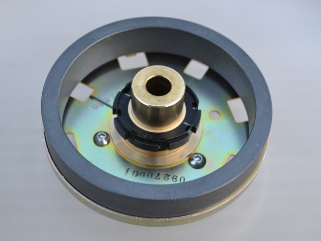
The platter components laid out. I tapped the Acrylic to accept M4 machine screws which will secure the magnet. The Brass adaptor to the right was made for me by a local model maker, it slides over the existing brass bush and is secured by grub screws. This is machined very accurately, centres the magnet and provides a platform for the position detection hub at the correct height.
The parts went together well, a very close fit with no play at all. I had marked the orientation of the sensor hub in relation to the magnet prior to removing them from the Technics Platter. I glued the sensor to the adaptor in the correct alignment, if necessary this can be adjusted by loosening the grub screws in the adaptor and rotating it.
The test bed has the motor PCB and regulator installed, I used a strip of Aluminium as a heat sink.
Ran into a bit of a problem, I purchased the PCB off Fleabay and it turns out to be quite a late version off a Mk5G. At some point Technics have changed the multi pin socket that connects the Start/Stop & 33/45 buttons, because the socket on the board is incompatible with the plug on the switch harness off a Mk2. Doh!
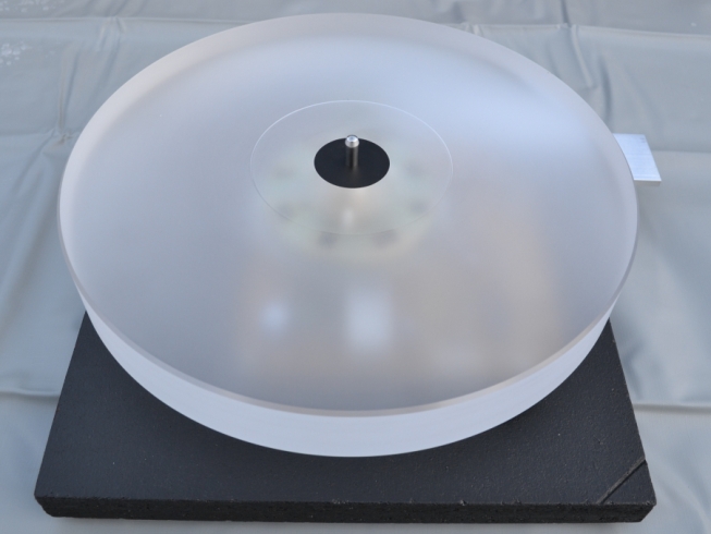
I lowered the new Platter into position with everything crossed. There was no crunching or grinding of coils, it went on smoothly and the magnet spins freely between the coils and the metal shield.
Well it certainly looks the part, the semi transparent nature of the textured Acrylic allows you to faintly make out the shape of the magnet and PCB which I think looks kind of cool, especially when the platter is spinning.
All I have to do now is rig up a power supply, solve the control harness socket issue and it should power up.
I removed the receptacles from the connector on the control harness and clipped them direct to the pins on the board. I heat shrinked every alternate connection to prevent them shorting. For the PSU, I couldn't wait for the correct leads and connectors to come through the post so I hard wired it for a trial. It powered up and runs perfect. The only tweak necessary was to give the brake about a quarter of a turn on the adjuster, this platter is 38mm thick Acrylic and weighs 3.5Kg which is approximately twice that of the stock Technics Platter.
Well that's the drive principle proven, Id better design a deck to put it in.
This is the deck mocked up in a CAD package. The taller platter means the arm has to stand on a block to bring the cartridge up to the right height. The plinth is going to be plywood this time and I am chamfering the edges to make it look slimmer, its actually 76mm thick. The "Terminator" Arm will be installed and this now has the new mounting base fitted, which will allow me to experiment with different wand lengths. Construction can start when I get my hands on some decent Birch Ply.............


 Reply With Quote


 Originally Posted by NRG

