-
 DIY PSU & Regulator
This DIY project is based on the ideas and schematics that Jim (6L6) put forward in his thread:
http://theartofsound.net/forum/showt...wer-Supply-DIY
For clarity Ive brought all the elements of my build together into one place and added further instructions for anyone wanting to try and build this version.
---------------------------------------------------------------------------------------------------------------------
STOP!
Before you put yourself or others in danger, think very carefully about whether you are qualified to carry out any of this work.
Art of Sound Electrical Safety Advice
The Art of Sound is an open forum for music lovers and a place where all members can share their views on music and the equipment used for its reproduction.
The forum also caters for those who are interested in the DIY aspect of everything related to the audio replay chain, and therefore there will always be a healthy number of DIY articles and discussions in threads across the forum. Given the number of these, it is not possible to monitor or moderate all technical aspects of posts made by members.
The Art of Sound would therefore like to remind all who read such articles that while we encourage discussions on all audio related DIY we cannot and will not accept liability for the information given on any DIY related matters contained in any thread or posts herein.
We strongly advise extreme caution when considering any modification or building projects described, especially those concerning any mains voltage related upgrades, earth modifications and/or any other high voltage related modifications or building projects.
Unless you are suitably qualified or otherwise capable of carrying out such modifications/suggestions, then we strongly advise you consult qualified personnel.
We would also like to remind all our members and readers that some or all of the modifications found within the threads and posts of the forum may not be legal in certain countries and therefore advice on the legalities or otherwise should be sought before carrying out such modifications.
-----------------------------------------------------------------------------------------------------------------------------------
We are basically taking the stock Technics Transformer and housing it in an external enclosure, thereby removing any noise and/or vibration it generates from the turntable. The external PSU is further enhanced by the addition of some fairly large smoothing capacitors. The rectifier is also removed from the turntable PCB and one incorporated into the external PSU, so only DC voltage is supplied to the turntable.
The stock on-board regulator is replaced by a better quality item based around an LM317, its small PCB is mounted in the same location as the original.
These simple and low cost improvements significantly upgrade the decks performance.
They make what is already a good deck noticeably better.
I produced PCBs for my build as shown below, anyone interested in purchasing a pair can contact me through email, details of which can be found on my website as per the footer. Please bear in mind, I produced these for my own use, the PCBs are not production standard, but are of a good prototyping quality, as can be seen in the picture. The rest of this build is based around these PCBs.

PSU
The first task is to remove the transformer and its PCB from the deck and mount the transformer in a suitable external enclosure, its small board isnt needed. Jim and others have covered mounting in an external box before so I wont repeat it.
The transformers come in different forms:
Illustrated below on the left is the North American type. The two blue wires are the AC supply to the transformer primary coil and the two yellow wires are the output from the secondary coil which will be attached to the new PSU PCB.
On the right we have a typical European Transformer. For 240V mains supply the Blue and Brown wires are connected to the supply, the Yellow wires are the output to connect to the PSU board. Note that these transformers have twin secondarys and for this supply voltage, they should be joined in series by connecting the Black and White wires, to produce the correct output.
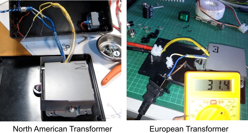
Pictures courtesy of 6L6 and Frankyc2003
With both Transformers, when connected to the correct supply voltage, the output across the Yellow leads should be around 32Vac, check this before connecting it to anything else.
Now lets look at producing the PSU board.
If you open the PDF file linked below, page 1 shows the schematic and parts list, page 2 shows the component layout and some assembly tips.
http://www.jkwynn.co.uk/Pics/PSU_Build.pdf
What you end up with should look like this:

The completed board stands 48mm tall including the pillars and can now be connected to the transformer and mounted in its case, I used a case from Maplins.co.uk order code BZ75S like so:

Check the output from the board is around 42Vdc.
Regulator
Moving on to the regulator construction, you will first have to remove the stock regulator and its leads connected to J1/J2/J3 positions on the main board.
The schematic for the new regulator and its parts list are on page 1 of the PDF file linked below and the component layout and building tips are on page 2.
http://www.jkwynn.co.uk/Pics/Reg_Build.pdf
The unloaded voltage from the Regulator can and should be checked prior to connecting to the deck. Connect the positive lead from the PSU to the Reg input and the negative from the PSU to the Reg ground. Measure across the Reg output and its ground, which should show around 20.5 to 20.7Vdc. When testing in this way, without a heat sink on the regulator, connect to the power for no more than around 20 seconds to avoid overheating.
To recap on the voltage checks throughout the build, you should make these measurements:
1). Check the output from the transformer is around 32Vac before connecting to the PSU board.
2). Check the output from the PSU board is around 42Vdc before connecting to the regulator board.
3). Check the unloaded output from the regulator is around 20.6Vdc as shown below before fitting to the deck.

The PSU can now be connected to the main TT PCB as shown below, note that the stock rectifier and pair of capacitors will have to be removed from this location first.

Picture courtesy of 6L6

Picture courtesy of 6L6
The lead used here for the connection is screened, note the wire joining the screen to the main grounding point.
I dont have the strobe pillar and its on off switch on my deck, if you wanted you could run the DC power coming in to the deck, through this switch before it goes to the main board.
I just use an on/off switch on my external PSU case to do the same job.
The regulator leads can now be soldered to the main board as per the PDF instructions and the small PCB mounted into its location with the aid of the spacer as below. A spot of heat sink thermal compound between the spacer and mounting boss is a good idea to improve heat transfer.

Remember Do not power up the deck with the platter removed, it should always be in place, because if you accidently hit start without it, you will fry the motor circuit.
Well thats all there is to it, and time for a big thank you to Jim (6L6) for coming up with the idea of this combination of upgrades and for his advice throughout my build, I am extremely happy with the outcome and performance.
Hopefully, by offering the PCBs and instructions, I have made the execution of the project a little more straight forward and professional looking for any competent DIYer that wants to build it. 
 Posting Permissions
- You may not post new threads
- You may not post replies
- You may not post attachments
- You may not edit your posts
-
Forum Rules


 Reply With Quote