+ Reply to Thread
Page 1 of 3 123 LastLast
Results 1 to 10 of 23

Thread: Pete's Lenco GL 75

  1. #1
    Join Date: Feb 2009

    Location: Stonehouse, Gloucestershire

    Posts: 723
    I'm Peter.

    Default Pete's Lenco GL 75

    Following on from the experiences of Beechy, I managed to get a Lenco GL 75. It's a bit shaggy, so I've cleaned it up a little but a lot more needs to be done.

    First, some piccies:
    From the top:


    Underneath:


    The wheel:


    I have a couple of aims with this. The first is just to get it working so that I can hear it. The second is to do some rewiring. The third will be putting it in a new plinth.

    The first aim is not as easy as I would like. The two tonearms I have both have rubbish tonearm wire - both have been cut very close to the arm so I can't connect them to the phono cables. So, first job is to rewire the tonearm! Having two tonearms becomes a bit more useful here as I can use one to experiment on - beginning with how to take one apart.

    The second aim will be helped by my local B&Q (closer than Maplin) - who sell two core cable. Not sure what to do about the phono cables yet.

    The plinth should be relatively easy after all that - especially as I will be following Beechy's lead and using butchers blocks to do the job.

    So, here begins my first steps into audio diy. I feel as if I have bitten off more than I can chew. But, I want to learn how to do this stuff, and no better way than the hard way. I'm hoping to call on the wealth of experience here and hoping you'll all be patient with my frequent very basic questions!

  2. #2
    Join Date: May 2008

    Location: A Strangely Isolated Place in Suffolk with Far Away Trains Passing By...

    Posts: 14,535
    I'm David.

    Default

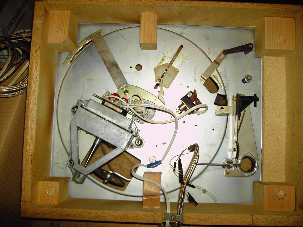
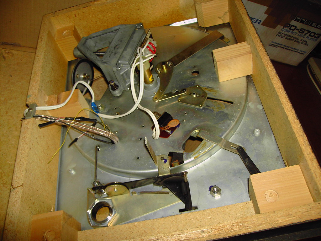
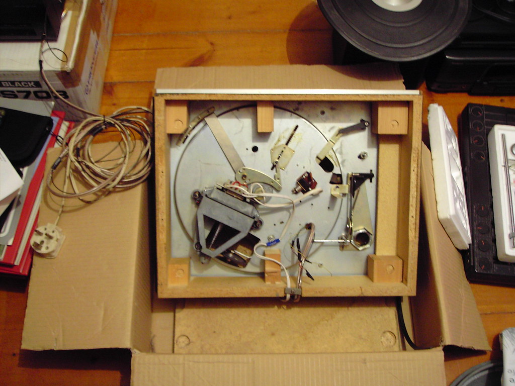
    The arm internal wires are fairly heavy gauge as tonearm wires go, but should still be serviceable ? The external wires to the amp have been done already. Don't forget to slacken the red motor transit screws and ensure the motor floats freely as best as possible.

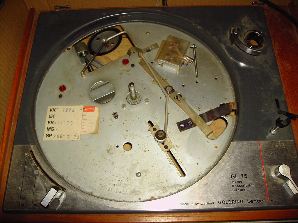
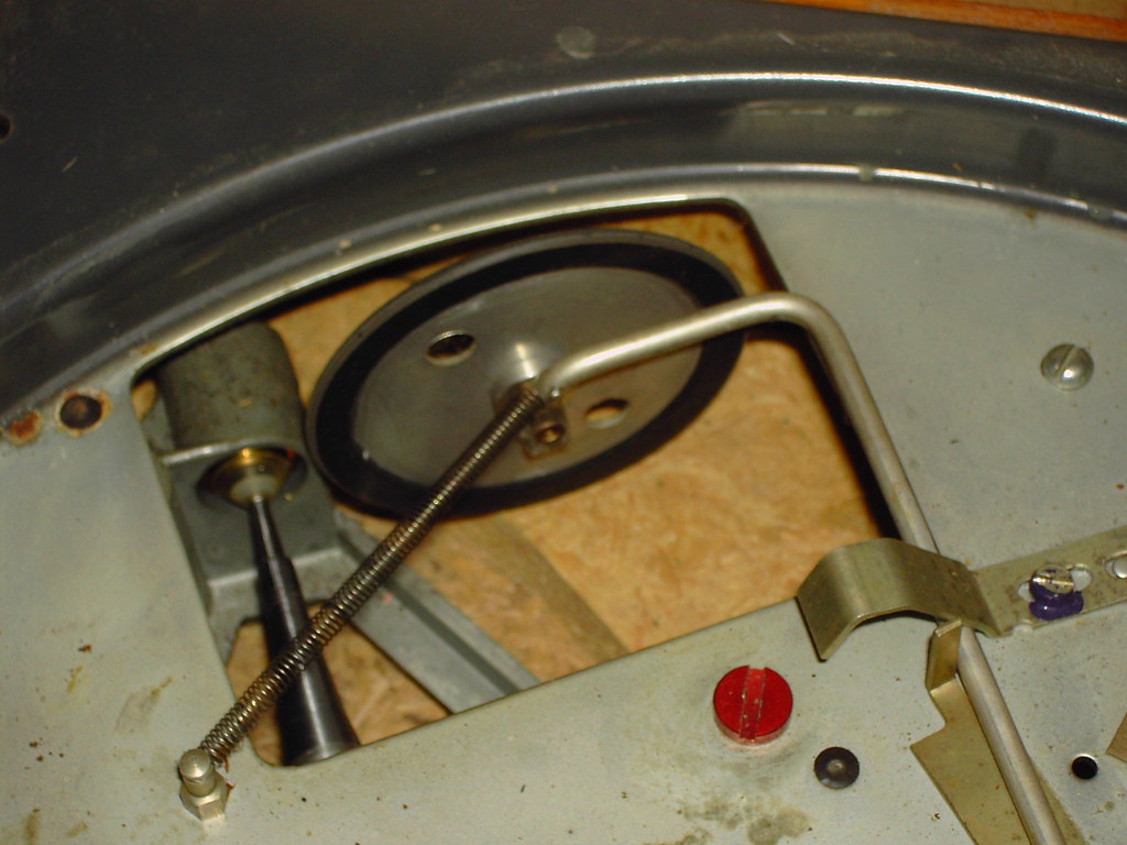
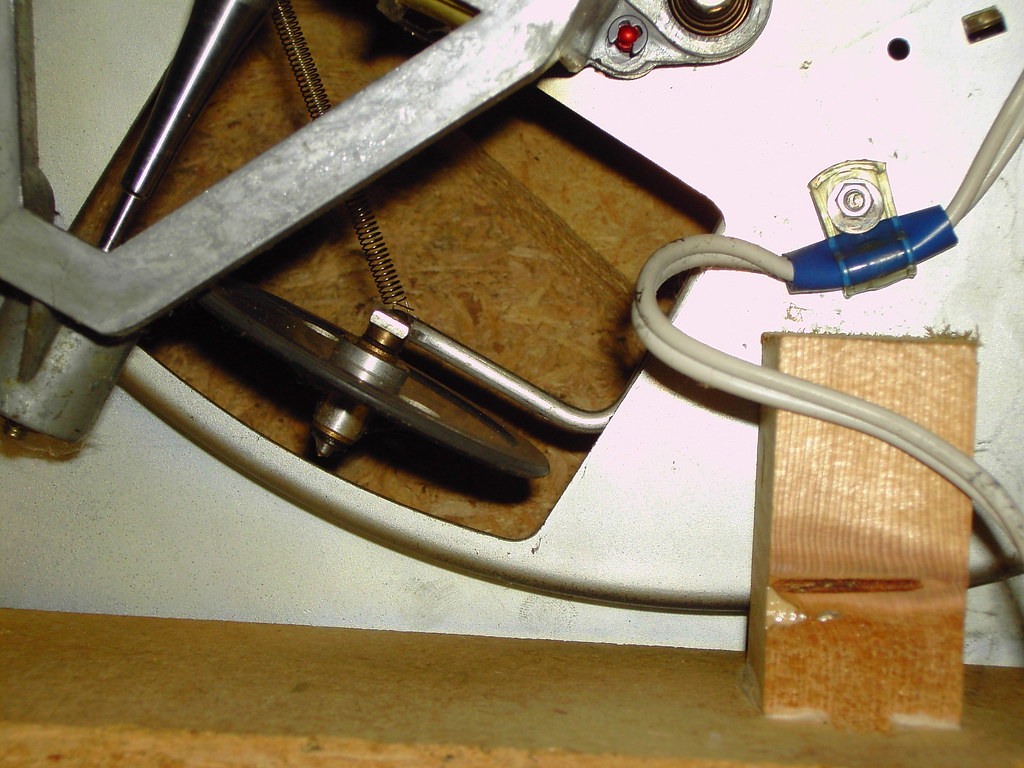
    The idler looks like a mid period one. The early ones had a solid plastic (?) inner and the later ones had four or five holes cut out of the inner. Carbon Tetrachloride was suggested to clean the motor pulley, underside of platter and the rubber tyre, although I've used switch cleaner solvent with no worries. Make sure to clean the under edge of the platter too to prevent the platter brake from squeaking loudly on switch-off....

    Regarding arm alternatives - I wonder if one of the Notts Analogue ones could be made to fit the hole? The price would be prohibitive though I suspect. I still think the L75 arm could be breathed on to good effect and if the arm/cart resonance is "only" 8 Hz with a Shure M75-ED, then there are many good carts under a ton which the arm should safely handle I think..
    Tear down these walls; Cut the ties that held me
    Crying out at the top of my voice; Tell me now if you can hear me

  3. #3
    Join Date: Feb 2009

    Location: Stonehouse, Gloucestershire

    Posts: 723
    I'm Peter.

    Default

    I should point out that I have never taken a tonearm apart, let alone a Lenco one. So, I have no idea which bits come apart and which bits I should be trying to take apart!

  4. #4
    Join Date: May 2008

    Location: A Strangely Isolated Place in Suffolk with Far Away Trains Passing By...

    Posts: 14,535
    I'm David.

    Default

    I don't even know if the socket can be removed from the lenco arm pipe...

    if you look at the rear of the arm under the rear counterweight rod, you'll see s screw. remove this, together with the U shaped washer it holds. If the arm cables are free, you can then lift the arm pipe and bearing-top off the arm pillar proper. This exposes the almost certainly knackered knife edge blocks and allows you to see the underside of the headshell socket, which may be bonded or riveted on, rather than screwed as jap arms are. watch the internal yellow arm earth wire, as stripping this is a nightmare to correct IIRC.

    If the arm is well and truly shagged, other samples can be got cheaply enough, so all is not lost. I rather like the look of the GL78 headshell too, with its holes in the top. I understand the GL85 shell fits too.
    Tear down these walls; Cut the ties that held me
    Crying out at the top of my voice; Tell me now if you can hear me

  5. #5
    Join Date: Feb 2009

    Location: Stonehouse, Gloucestershire

    Posts: 723
    I'm Peter.

    Default

    Hmm - I'll take some photos of the arms I have. But, from what you have said, and looking at them, I think you may be right about them not be re-wirable. Which means getting another arm. That'll teach me to go buying something without fully understanding what I need!

  6. #6
    Join Date: Apr 2008

    Location: Chester

    Posts: 429

    Default

    Plenty of advice based on good experience here.

    http://www.lencoheaven.net/forum/index.php

    I'm also in the process of doing up a Lenco, and these guys have already covered all the angles.

  7. #7
    Join Date: Feb 2009

    Location: Stonehouse, Gloucestershire

    Posts: 723
    I'm Peter.

    Default

    Yes, I'm going to post there soon as well. I've had a look around that great site but I've not found too much on tonearms yet. The general advice seems to be to replace it. But, I'm a contrary bugger and would like to hear what the original sounds like before moving on.

  8. #8
    Join Date: Feb 2009

    Location: Stonehouse, Gloucestershire

    Posts: 723
    I'm Peter.

    Default

    Well, I'm not getting very far, so far.
    I have taken some photos of the arms I have, but they are next to rubbish so I need to try again.

    For now, though, I'm still puzzling over the possibility of rewiring the arm. The arms I have are both slightly different, but I suppose the mechanics will be the same for the both of them. My first guess is that the end of the arm which the headshell plugs in to might be removable. Does this sound right?
    Logic suggests that the arm had to be wired in the first place! So, how was it done? Any clues?

    Dave, I did read your post, but I'm not sure I understand it. Perhaps photos will help. I'll get onto that shortly.

    I'm very puzzled (and slightly frustrated!)

  9. #9
    Join Date: May 2008

    Location: A Strangely Isolated Place in Suffolk with Far Away Trains Passing By...

    Posts: 14,535
    I'm David.

    Default

    Usually, the socket can be removed from the arm pipe, but I don't think it's possible with the L69 and L75 arms, as the socket looks bonded or riveted on. same with the arm earth tab, which seems to be riveted into the pipe. The headshell wires are easily replaced, however. As you can see, the wires from deck to amp can easily be replaced too.
    Tear down these walls; Cut the ties that held me
    Crying out at the top of my voice; Tell me now if you can hear me

  10. #10
    Join Date: Feb 2009

    Location: Stonehouse, Gloucestershire

    Posts: 723
    I'm Peter.

    Default

    Yes, and I can see how they can be done and am happy that doing so should be simple. My problem is with the wires coming out of the armpipe. For both arms they are too short. So, I'm trying to find out how to get round this without buying another arm.

    The other problem I will have is with the earth wire - which looks like it is soldered to the armpipe (oops, that what you just said!), so I need to get me a soldering iron soon as well.

+ Reply to Thread
Page 1 of 3 123 LastLast

Posting Permissions

  • You may not post new threads
  • You may not post replies
  • You may not post attachments
  • You may not edit your posts
  •