New Member
Location: India
Posts: 21
I'm krishna.
What does this do?
Location: fuck off
Posts: 2,033
I'm fuckoff.
Neat work, how do they sound?
New Member
Location: India
Posts: 21
I'm krishna.
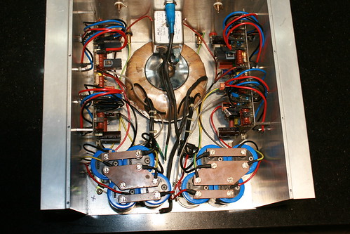
Holes for output devices drilled on heat sinks using a TO3 jig. Input and speaker binding posts holes done and connectors mounted.
IMG_4448 by hydrovac, on Flickr
IMG_4366 by hydrovac, on Flickr
IMG_4556 by hydrovac, on Flickr
IMG_4481 by hydrovac, on Flickr
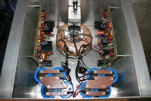
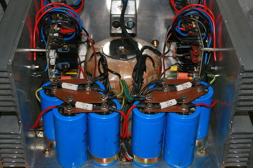
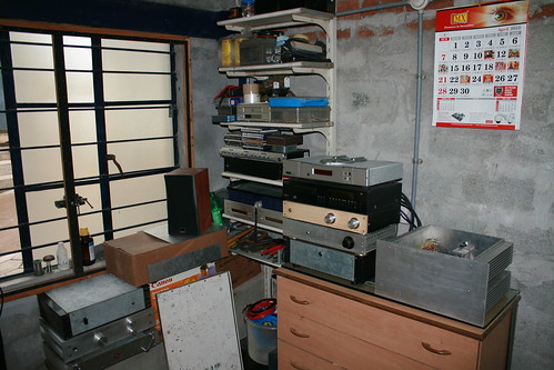
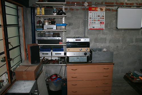
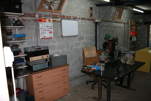
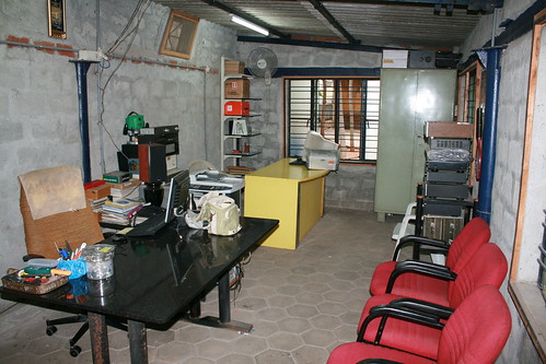
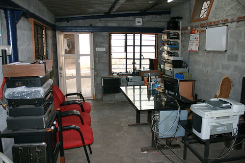
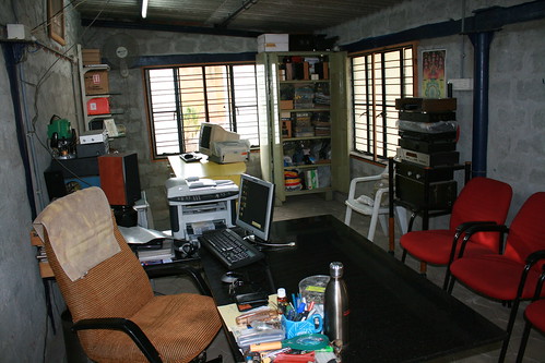
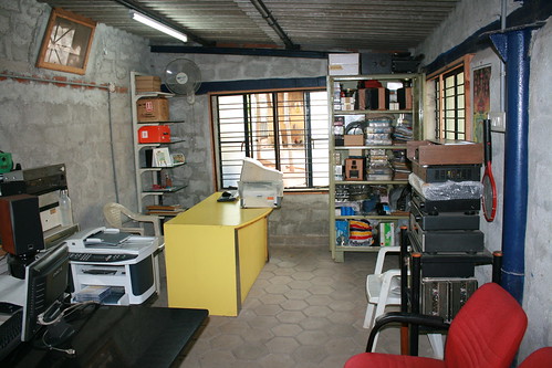
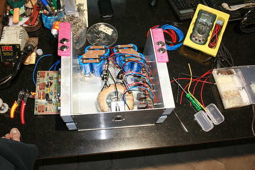
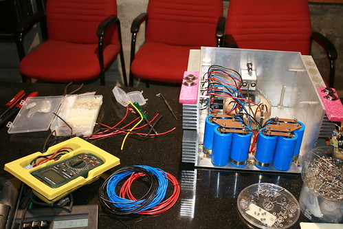
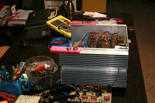
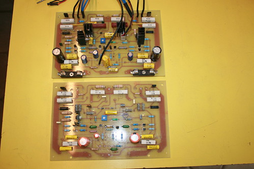
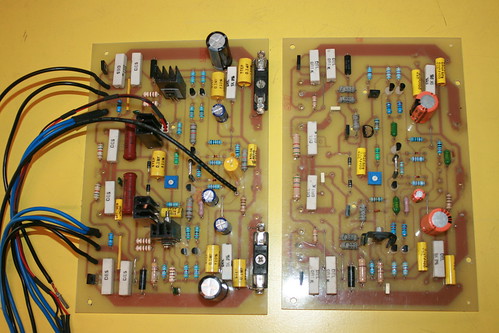
This is the den for our hobby & passion, and where all our classics come to life.
IMG_4399 by hydrovac, on Flickr
IMG_4398 by hydrovac, on Flickr
IMG_4397 by hydrovac, on Flickr
IMG_4396 by hydrovac, on Flickr
IMG_4315 by hydrovac, on Flickr
IMG_4314 by hydrovac, on Flickr
IMG_4313 by hydrovac, on Flickr
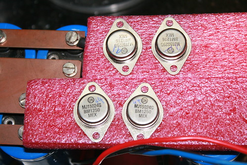
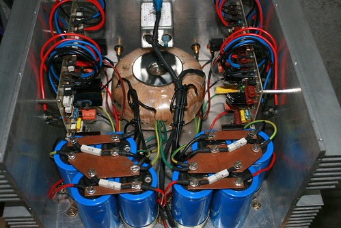
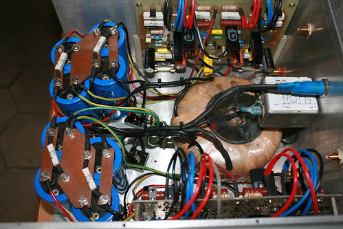
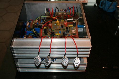
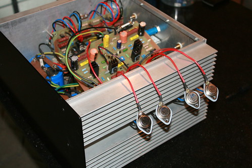
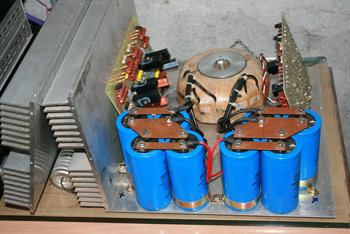
Power transistors mounting process and progress.
IMG_4420 by hydrovac, on Flickr
IMG_4412 by hydrovac, on Flickr
IMG_4409 by hydrovac, on Flickr
IMG_4416 by hydrovac, on Flickr
IMG_4414 by hydrovac, on Flickr
IMG_4412 by hydrovac, on Flickr
IMG_4449 by hydrovac, on Flickr
IMG_4442 by hydrovac, on Flickr
New Member
Location: India
Posts: 21
I'm krishna.
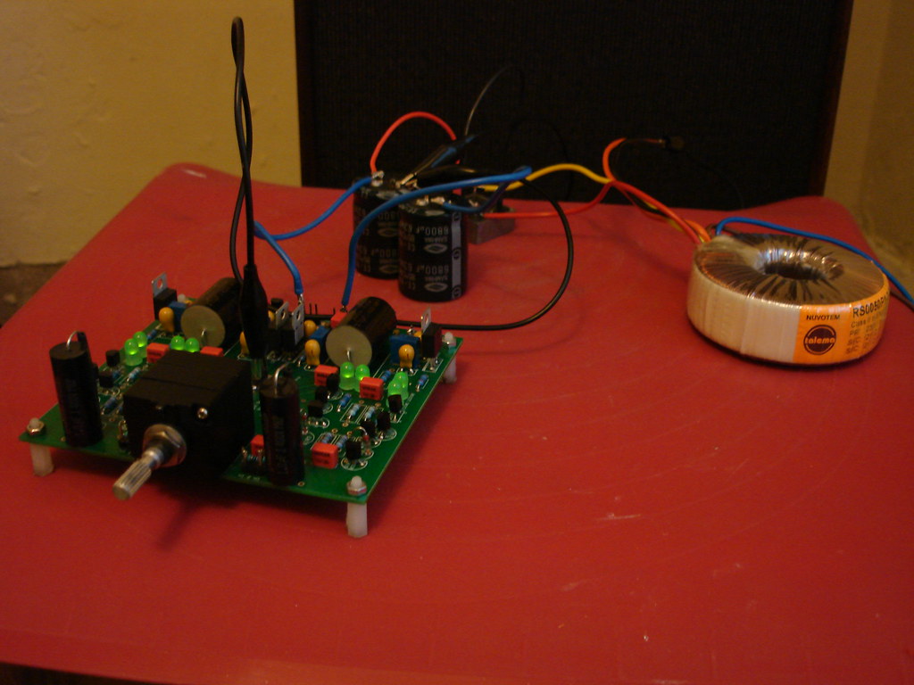
Thanks realysm42,Originally Posted by realysm42

The prototype sounded really pure with low noise floor. Even audiophile grade prompting me to build one with soft start and speaker protection against DC.
The specs are as below:
POWER OUTPUT: 200W rms/8 ohm
310W rms/4 ohm
800W rms/8 ohm (Bridge mode)
FREQUENCE RESPONSE: 20HZ-20KHZ +/-0.5dB
INPUT SENSITIVITY: 1V for 200W/300W
HUM AND NOISE: -105dB
THD: <0.1%
DAMPING FACTOR: 65
New Member
Location: India
Posts: 21
I'm krishna.
New Member
Location: India
Posts: 21
I'm krishna.
Hi friends,
Sorry for the long gap in my post as I was preoccupied with other commitments. In continuation to my earlier posts, here is progress in amp build.
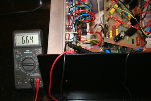
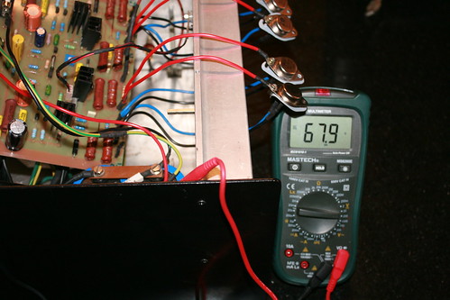
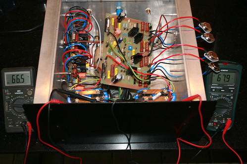
Checking the DC rail voltages: Left channel, Right channel, both channels
IMG_4645 by hydrovac, on Flickr
IMG_4646 by hydrovac, on Flickr
IMG_4648 by hydrovac, on Flickr
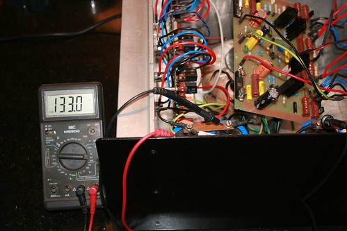
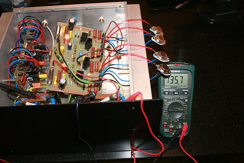
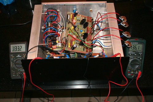
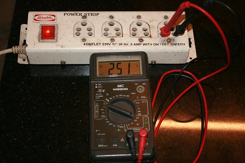
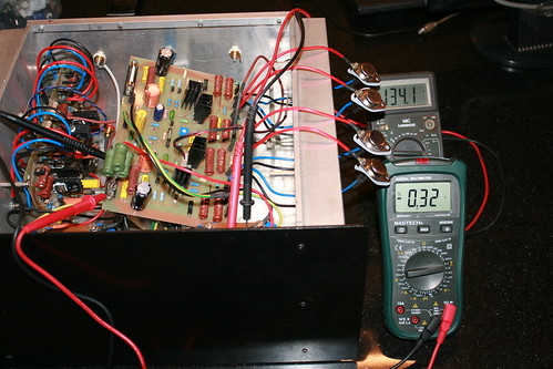
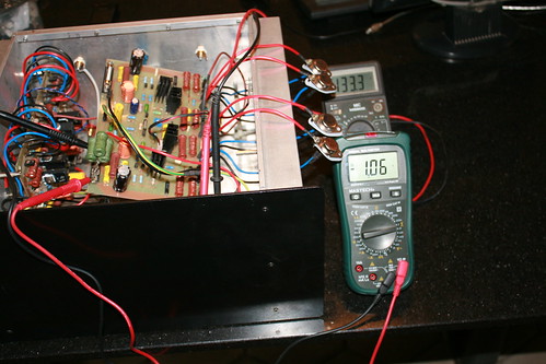
Checking full rail voltages: Left channel, Right channel, - Ve and +Ve rails
IMG_4652 by hydrovac, on Flickr
IMG_4653 by hydrovac, on Flickr
IMG_4655 by hydrovac, on Flickr
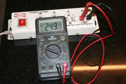
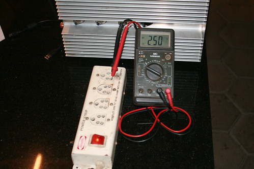
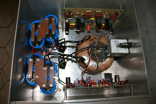
I am supposed to get around +62 and -62 volts DC on rails. The increase in reading is because of the mains input voltage (250 volts AC). Toroidal transformer winding is rated for 230 volts primary.
IMG_4682 by hydrovac, on Flickr
IMG_4686 by hydrovac, on Flickr
IMG_4683 by hydrovac, on Flickr
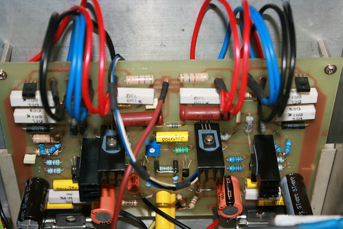
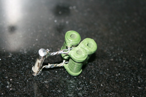
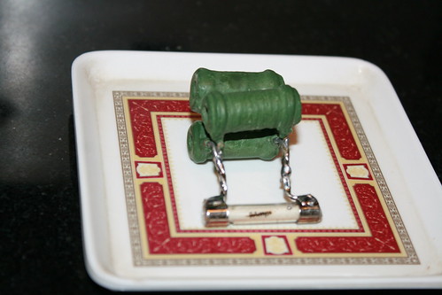
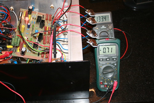
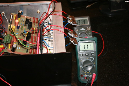
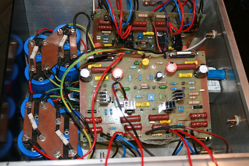
Setting the quiescent bias current for output stage:
Fabricated a 10 ohm 5 watt wire wound resistor suitable for the fuse holder.
IMG_4671 by hydrovac, on Flickr
IMG_4674 by hydrovac, on Flickr
Inserted in +Ve side holder and switched on the power. Adjusted the trim pot to get, 1.0 volt across the resistor.
IMG_4658 by hydrovac, on Flickr
IMG_4660 by hydrovac, on Flickr
IMG_4661 by hydrovac, on Flickr
IMG_4662 by hydrovac, on Flickr
IMG_4657 by hydrovac, on Flickr
IMG_4659 by hydrovac, on Flickr
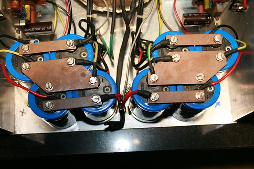
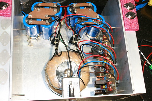
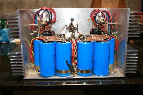
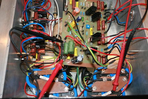
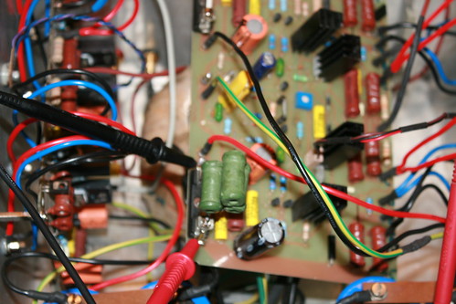
You can see the thermal sensing bias transistors mounted mid way between the power transistors on the heat sink. Good going so far.
IMG_4678 by hydrovac, on Flickr
IMG_4680 by hydrovac, on Flickr
IMG_4679 by hydrovac, on Flickr
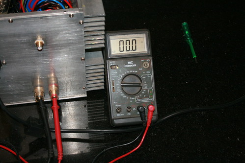
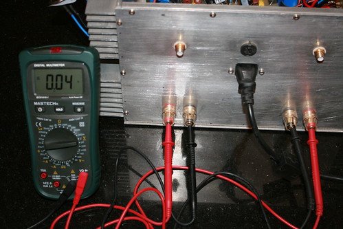
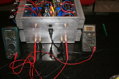
Now, looking at output side. Measuring the speaker output terminals for DC.
IMG_4669 by hydrovac, on Flickr
IMG_4668 by hydrovac, on Flickr
IMG_4667 by hydrovac, on Flickr
Left channel looks clean without any DC. But right channel is showing 0.04 volts. There seems to be a hitch somewhere. I will get back with updates after trouble shooting.
Thanks for looking and following the post.
Senior Member

Location: Hartlepool UK
Posts: 1,640
I'm Alan.
Nice jobhave you had a listen yet?.
40mv dc offset isnt that bad both of mine are 20-30mv could be a slightly leaky cap try C7. I would have used 0.1% precission matched all the resistors in the ist stage as well.
Not sure I understand the method of setting the Bias current ? normally its a mv reading accross the emitter resistors or disconnect the +ve lead to the board and measure the total current draw (unloaded output) in ma
Alan
New Member
Location: India
Posts: 21
I'm krishna.
Hi Alan,
Thanks for that. I replaced the C7 cap with a new one and now its reading 1.5 mv on right ch and 2.8 Milli volts left ch, in 200mv range of multimeter. Shouldn't this be zero volts? Can I connect the speaker in a condition like this?
The author suggested to setup the Bias as shown in the link.
http://users.otenet.gr/~athsam/300w.htm
I will have to remount the transistors and give it a listening test.
Last edited by hydrovac; 03-08-2013 at 10:42.
Senior Member
Location: Hartlepool UK
Posts: 1,640
I'm Alan.
Your Dc offset is excellent and will not damage your speakers dont worry
Mine ar 30ma in both channels as I use a Mil spec wet tants in the feed back position and they are a bit leaky as well but it still will do no damage if mine goes over 50ma I will change the caps but many say as high as 100ma is still OK.
Alan
Senior Member
Location: South downs
Posts: 3,477
I'm James.
ITS ALIVE !!!
Finally got around to fitting new CCD's & the B4 lives
As you can see I paid special attention to the wiring

 Posting Permissions


 Reply With Quote